Reversing Relay
Installation and Operation
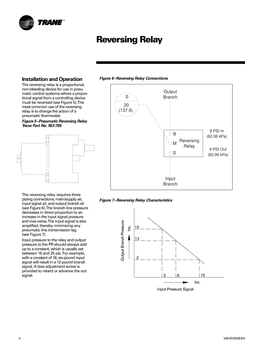
Figure 6–Reversing Relay Connections
The reversing relay is a proportional,
Figure 5–Pneumatic Reversing Relay Trane Part No. RLY-755
Output
SBranch
20
(137.9)
B
M Reversing
Relay
S
9 PSI In
(62.06 kPa)
9 PSI Out
(62.06 kPa)
The reversing relay requires three piping connections: main/supply air, input signal air, and output branch air (see Figure 6).The branch line pressure decreases in direct proportion to an increase in the input signal pressure and
(see Figure 7).
Input pressure to the relay and output pressure to the PR should always add up to a constant, which is usually set between 16 and 25 psi. For example, with a constant of 18,
Input
Branch
Figure 7–Reversing Relay Characteristics
Pressure | Inc. | 15 | |
Branch |
|
| 12 |
Output |
|
| 3 |
|
|
| |
3 | 6 | 15 |
Inc.
Input Pressure Signal
4 |