Calibration
Procedures
Calibration Procedure (Steps
1.Be sure the PVR is installed correctly and that all connections are hooked up to the proper ports. See Figure 9 for unit application.
2.Remove the caps on the tees which are connected to the lines to the flow sensor. Connect a
3.Remove the thermostat line and connect a hand pump with a
4.Tee a
Normally-OpenValve
Normally-Open Valve
5.Set port “T” at 0 psi.
6.Monitor the delta P and adjust the
7.Set port “T” input at 16 psi or greater with the hand pump.
8.Monitor the delta P and adjust the
9.Set port “T” at 0 psi.
10.Monitor the minimum flow delta P. If it is not correct, adjust the
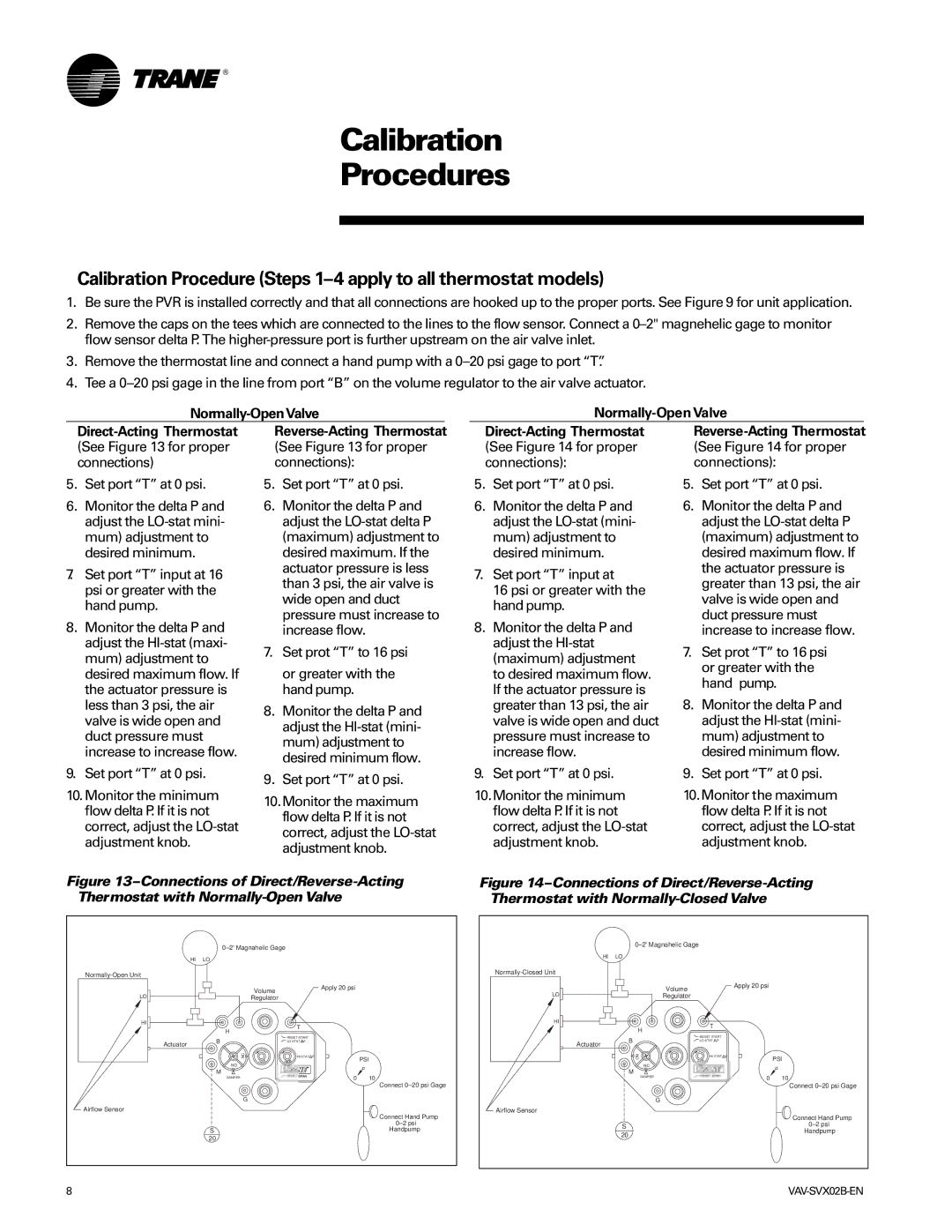
Reverse-Acting Thermostat (See Figure 13 for proper connections):
5.Set port “T” at 0 psi.
6.Monitor the delta P and adjust the
7.Set prot “T” to 16 psi
or greater with the hand pump.
8.Monitor the delta P and adjust the
9.Set port “T” at 0 psi.
10.Monitor the maximum flow delta P. If it is not correct, adjust the
5.Set port “T” at 0 psi.
6.Monitor the delta P and adjust the
7.Set port “T” input at
16 psi or greater with the hand pump.
8.Monitor the delta P and adjust the
9.Set port “T” at 0 psi.
10.Monitor the minimum flow delta P. If it is not correct, adjust the
5.Set port “T” at 0 psi.
6.Monitor the delta P and adjust the
7.Set prot “T” to 16 psi or greater with the hand pump.
8.Monitor the delta P and adjust the
9.Set port “T” at 0 psi.
10.Monitor the maximum flow delta P. If it is not correct, adjust the
Figure | Figure |
Thermostat with | Thermostat with |
0±2© Magnahelic Gage
HI LO
0±2© Magnahelic Gage
HI LO
LO ![]()
![]()
Volume | Apply 20 psi |
Regulator |
|
Normally-Closed Unit
LO ![]()
![]()
Volume
Regulator
Apply 20 psi
HI
T |
H |
HI
H
![]() T
T
Actuator
![]() Airflow Sensor
Airflow Sensor
B | RESET START |
|
LO STAT P |
| |
NC | HI STAT P | PSI |
I C |
| |
NO |
|
|
M | 0 | 10 |
DAMPER | ||
|
Connect 0±20 psi Gage
| G |
| Connect Hand Pump |
| 0±2 psi |
S | Handpump |
20 |
|
Actuator
Airflow Sensor
![]() RESET START
RESET START
B![]() LO STAT
LO STAT ![]() P
P
NO |
| HI STAT P |
I | C | I N R |
NC |
|
|
M |
|
|
DAMPER |
|
|
G
S 20
PSI
0 10
Connect 0±20 psi Gage
![]() Connect Hand Pump
Connect Hand Pump
0±2 psi
Handpump
8 |