Constant-Volume Dual-Duct Calibration (3011)
ConstantVolume Dual-Duct Calibration (3011)
This calibration procedure is used when a constant volume of air must be maintained through a unit. On a dual- duct unit, a
This PVR does not require a thermostat connected to the PVR.
The following procedure must be used when calibrating a
1.Set
2.Set LO thermostat (maximum) to the desired maximum flow on the heating deck.
3.Set
4.Set HI thermostat (minimum) to the desired minimum flow on the heating deck.
5.Set LO thermostat adjustment knob on cooling deck (CV deck) to desired
6.Exercise the system to check flows for proper operation.
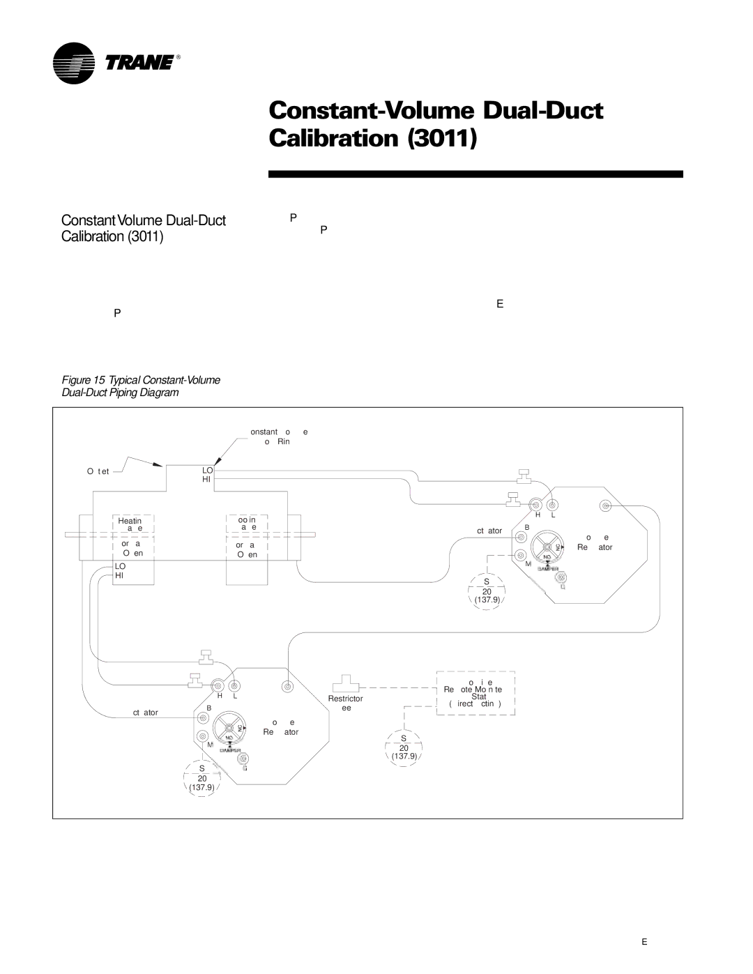
Figure 15–Typical Constant-Volume
Dual-Duct Piping Diagram
|
|
|
|
|
|
|
|
| |
|
|
|
| Flow Ring |
|
|
|
|
|
Outlet |
| LO |
|
|
|
|
|
|
|
|
| HI |
|
|
|
|
|
|
|
|
|
| Cooling |
|
| H | L | T | |
| Heating |
|
|
|
| ||||
|
|
|
|
|
|
| |||
| a ve |
| Valve |
| Actuator | B |
| Volume | |
|
|
|
|
|
|
|
| ||
| Normally- |
| Normally- |
|
|
|
| ||
|
|
|
|
|
| Regulator | |||
| Open |
|
| Open |
|
|
|
|
|
| LO |
|
|
|
|
| M |
|
|
| HI |
|
|
|
| S |
|
|
|
|
|
|
|
|
|
|
|
| |
|
|
|
|
|
| 20 |
|
|
|
|
|
|
|
|
| (137.9) |
|
|
|
|
|
|
|
|
|
|
|
| |
|
| H |
| T |
|
|
|
| |
|
| L | Restrictor |
|
|
| |||
|
|
|
|
|
| ||||
| Actuator | B |
|
| Tee |
|
|
| |
|
|
|
|
|
|
| |||
|
|
|
|
|
|
|
|
| |
|
|
|
| Volume |
|
|
|
|
|
|
|
|
| Regulator |
| S |
|
|
|
|
| M |
|
|
|
|
|
| |
|
|
|
|
| 20 |
|
|
| |
|
|
|
|
|
|
|
|
| |
|
|
|
|
|
| (137.9) |
|
|
|
|
| S |
| G |
|
|
|
|
|
|
| 20 |
|
|
|
|
|
|
|
|
| (137.9) |
|
|
|
|
|
|
|
14 |
|
|
|
|
|
|
|
| |
