Reversing Relay
Calibration
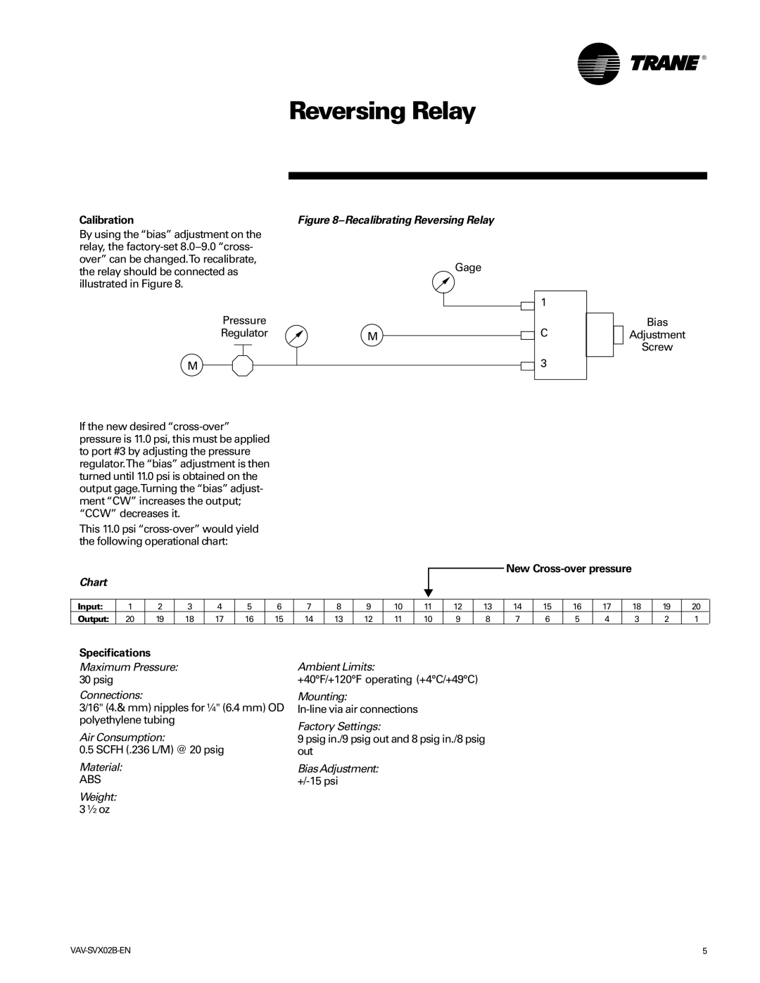
By using the “bias” adjustment on the relay, the
Pressure
Regulator
M
Figure 8–Recalibrating Reversing Relay
Gage
1
M ![]()
![]() C
C
3
Bias
Adjustment
Screw
If the new desired
This 11.0 psi
New Cross-over pressure
Chart
Input: | 1 | 2 | 3 | 4 | 5 | 6 | 7 | 8 | 9 | 10 | 11 | 12 | 13 | 14 | 15 | 16 | 17 | 18 | 19 | 20 |
Output: | 20 | 19 | 18 | 17 | 16 | 15 | 14 | 13 | 12 | 11 | 10 | 9 | 8 | 7 | 6 | 5 | 4 | 3 | 2 | 1 |
Specifications
Maximum Pressure: 30 psig
Connections:
3/16" (4.& mm) nipples for ¼" (6.4 mm) OD polyethylene tubing
Air Consumption:
0.5 SCFH (.236 L/M) @ 20 psig
Material:
ABS
Weight: 3 ½ oz
Ambient Limits:
+40°F/+120°F operating (+4°C/+49°C)
Mounting:
Factory Settings:
9 psig in./9 psig out and 8 psig in./8 psig out
Bias Adjustment:
5 |
