Installation -- Continued
Connect the Fiber Cable
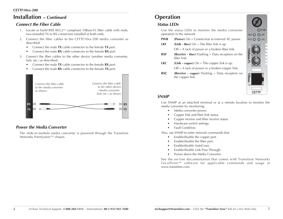
1.Locate or build IEEE 803.2™ compliant
2.Connect the fiber cables to the
•Connect the male TX cable connector to the female TX port.
•Connect the male RX cable connector to the female RX port.
3.Connect the fiber cables to the other device (another media converter, hub, etc.) as described:
•Connect the male TX cable connector to the female RX port.
•Connect the male RX cable connector to the female TX port.
Operation
Status LEDs
Use the status LEDs to monitor the media converter operation in the network
PWR | (Power) On = Connection to external AC power. |
LKF | (Link - fiber) On = The fiber link is up. |
| Off = A lack of power or a broken fiber link. |
RXF | (Receive - fiber) Flashing = Data reception on the |
| fiber link. |
LKC | (Link - copper) On = The copper link is up. |
| Off = A lack of power or a broken copper link. |
RXC | (Receive - copper) Flashing = Data reception on |
| the copper link. |
![]() PWR
PWR
RXF ![]()
![]() LKF
LKF
RXC ![]()
![]() LKC
LKC
Connect the fiber cable to the media converter as shown.
RX
TX
Connect the fiber cable to the other device (media converter, hub, etc.) as shown
RX
![]() TX
TX
SNMP
Use SNMP at an attached terminal or at a remote location to monitor the media converter by monitoring:
• | Media converter power. |
• Copper link and fiber link status. | |
• Copper receive and fiber receive status. | |
• | Hardware switch settings. |
Power the Media Converter
The
• | Fault Condition. |
Also, use SNMP to enter network commands that:
•Enable/disable the copper port .
•Enable/disable the fiber port.
•Enable/disable AutoCross.
•Enable/disable Link
•Power down the Media Converter.
See the
4 | techsupport@transition.com | 5 |
