CPSMM-120 Single-Slot Master Management Module
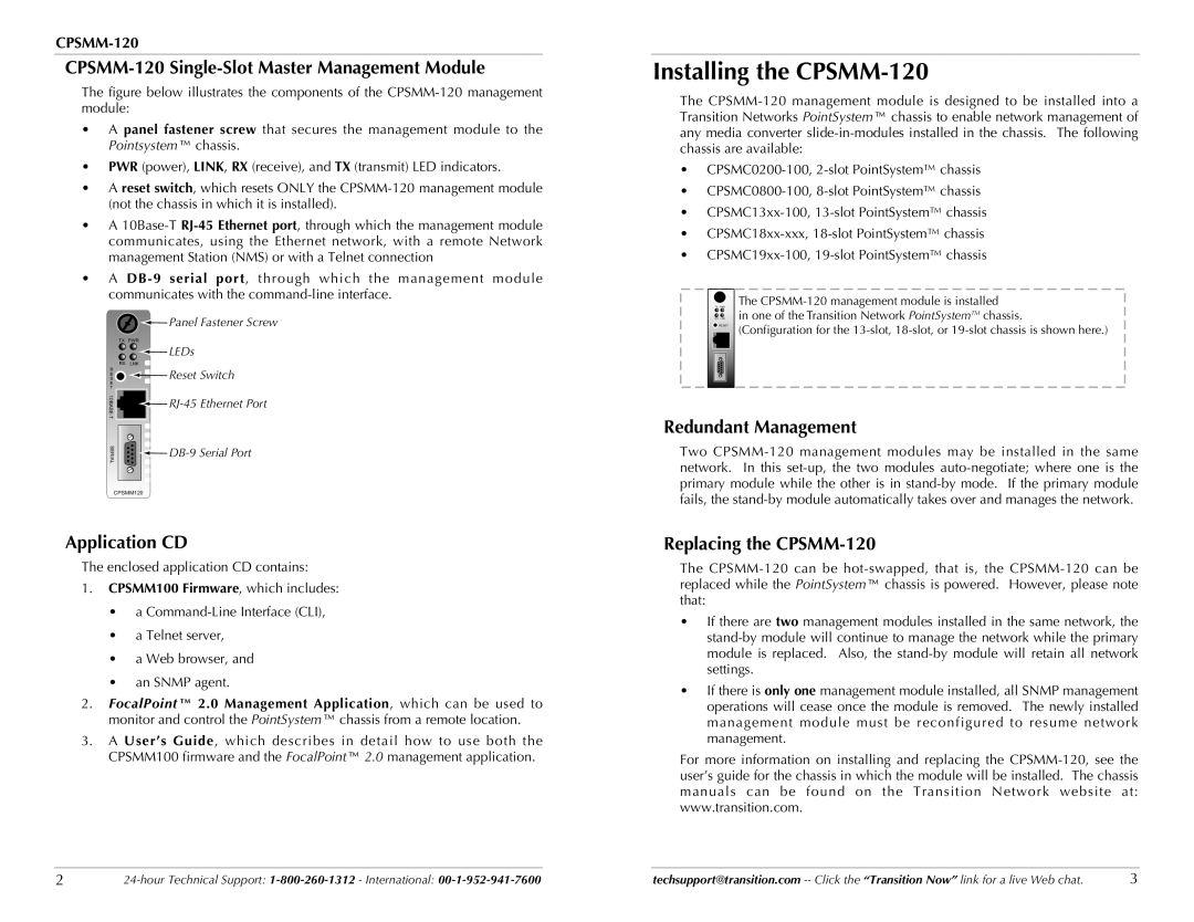
The figure below illustrates the components of the CPSMM-120 management module:
•A panel fastener screw that secures the management module to the Pointsystem™ chassis.
•PWR (power), LINK, RX (receive), and TX (transmit) LED indicators.
•A reset switch, which resets ONLY the CPSMM-120 management module (not the chassis in which it is installed).
•A 10Base-T RJ-45 Ethernet port, through which the management module communicates, using the Ethernet network, with a remote Network management Station (NMS) or with a Telnet connection
•A DB-9 serial port, through which the management module communicates with the command-line interface.
![]() Panel Fastener Screw
Panel Fastener Screw
TX PWR |
|
| LEDs |
RX LNK |
|
R | Reset Switch |
S | |
E |
|
E |
|
T |
|
| |
SERIAL | |
| |
CPSMM120 |
|
Application CD
The enclosed application CD contains:
1.CPSMM100 Firmware, which includes:
•a
•a Telnet server,
•a Web browser, and
•an SNMP agent.
2.FocalPoint™ 2.0 Management Application, which can be used to monitor and control the PointSystem™ chassis from a remote location.
3.A User’s Guide, which describes in detail how to use both the
CPSMM100 firmware and the FocalPoint™ 2.0 management application.
Installing the CPSMM-120
The
•
•
•
•
•
| TX PWR | The | |
| RX LNK | in one of the Transition Network PointSystemTM chassis. | |
| RESET | (Configuration for the | |
|
|
|
|
|
|
|
|
|
|
|
|
|
|
|
|
Redundant Management
Two
Replacing the CPSMM-120
The
•If there are two management modules installed in the same network, the
•If there is only one management module installed, all SNMP management operations will cease once the module is removed. The newly installed management module must be reconfigured to resume network management.
For more information on installing and replacing the
2 | techsupport@transition.com | 3 |
