CPSMP-130 & CPSMP-140

READ AND FOLLOW ALL WARNING NOTICES & INSTRUCTIONS MARKED ON THE PRODUCT OR INCLUDED IN THE MANUAL.

CAUTION: All installation and service must be performed by qualified service personnel.

CAUTION: Wear a grounding device and observe electrostatic discharge precautions when installing or servicing the power supply module. Failure to observe this caution could result in damage to, and subsequent failure of, the power supply module.

The Power Supply Module in the 13-Slot Chassis

CPSMP-130 Power Supply (48-VDC)

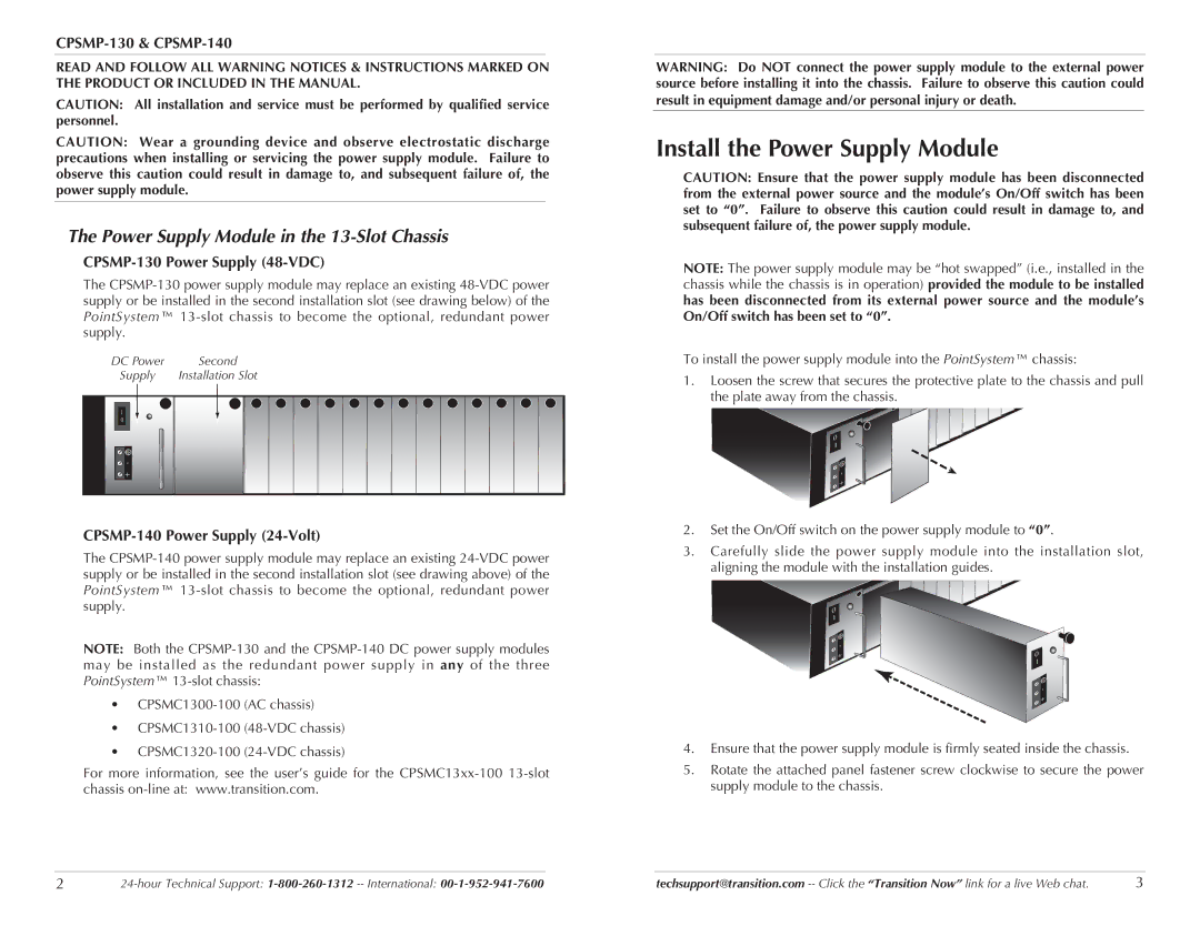
The CPSMP-130 power supply module may replace an existing 48-VDC power supply or be installed in the second installation slot (see drawing below) of the PointSystem™ 13-slot chassis to become the optional, redundant power supply.

DC Power

Second

Supply

Installation Slot

I

0

-

+

CPSMP-140 Power Supply (24-Volt)

The CPSMP-140 power supply module may replace an existing 24-VDC power supply or be installed in the second installation slot (see drawing above) of the PointSystem™ 13-slot chassis to become the optional, redundant power supply.

NOTE: Both the CPSMP-130 and the CPSMP-140 DC power supply modules may be installed as the redundant power supply in any of the three PointSystem™ 13-slot chassis:

CPSMC1300-100 (AC chassis)

CPSMC1310-100 (48-VDC chassis)

CPSMC1320-100 (24-VDC chassis)

For more information, see the user’s guide for the CPSMC13xx-100 13-slot chassis on-line at: www.transition.com.

WARNING: Do NOT connect the power supply module to the external power source before installing it into the chassis. Failure to observe this caution could result in equipment damage and/or personal injury or death.

Install the Power Supply Module

CAUTION: Ensure that the power supply module has been disconnected from the external power source and the module’s On/Off switch has been set to “0”. Failure to observe this caution could result in damage to, and subsequent failure of, the power supply module.

NOTE: The power supply module may be “hot swapped” (i.e., installed in the chassis while the chassis is in operation) provided the module to be installed has been disconnected from its external power source and the module’s On/Off switch has been set to “0”.

To install the power supply module into the PointSystem™ chassis:

1.Loosen the screw that secures the protective plate to the chassis and pull the plate away from the chassis.

0 I

-+

2.Set the On/Off switch on the power supply module to “0”.

3.Carefully slide the power supply module into the installation slot, aligning the module with the installation guides.

0 I

-


+

0


I

- +

4.Ensure that the power supply module is firmly seated inside the chassis.

5.Rotate the attached panel fastener screw clockwise to secure the power

supply module to the chassis.

2

24-hour Technical Support: 1-800-260-1312-- International: 00-1-952-941-7600

techsupport@transition.com -- Click the “Transition Now” link for a live Web chat.

3

Page 2
Image 2
Transition Networks Install the Power Supply Module, CPSMP-130 & CPSMP-140, CPSMP-130 Power Supply 48-VDC

CPSMP-130, CPSMP-140 specifications

Transition Networks is known for its innovative networking solutions, and the CPSMP-130 and CPSMP-140 models stand as prime examples of this commitment to quality. These two products belong to the company's series of media converters and are specifically designed to facilitate seamless connectivity between different network types, particularly in environments requiring robust performance and increased flexibility.

The CPSMP-130 model is a feature-rich, unmanaged media converter that enables users to convert fiber optic signals to Ethernet signals, ideal for extending network reach without compromising speed or performance. With its support for both single-mode and multi-mode fibers, this model accommodates varying distance requirements, making it suitable for both local area networks (LAN) and wide area networks (WAN). One of its standout features is the auto-sensing capability, which automatically adjusts to the optimal speed and duplex mode for connected devices, ensuring efficient communication.

The CPSMP-140 takes the functionality of the CPSMP-130 a step further by offering managed capabilities. This model allows for deeper network management and monitoring, providing features such as link monitoring, port statistics, and VLAN (Virtual Local Area Network) support. Such functionalities enhance the users' ability to tailor their network according to specific needs, ensuring optimal performance and security. The CPSMP-140 facilitates a high level of network performance with its support for Gigabit Ethernet, ensuring that data can be transmitted at high speeds over fiber connections.

One of the key characteristics shared between the CPSMP-130 and CPSMP-140 models is their robust construction, designed to withstand harsh environmental conditions. This makes them suitable for deployment in industrial or outdoor settings where reliability is paramount. Additionally, both models feature LED indicators for easy status monitoring, providing users with quick insights into operational status and troubleshooting.

Both media converters support a range of standards, ensuring compatibility with a myriad of devices, which is vital in today’s interconnected world. Their plug-and-play nature allows for easy installation and use without requiring extensive technical expertise. Furthermore, they come with various power options, including PoE (Power over Ethernet), enhancing their versatility and ease of deployment.

In summary, the Transition Networks CPSMP-130 and CPSMP-140 models are excellent solutions for organizations seeking reliable, high-performance connectivity solutions in diverse networking environments. With their blend of robust features and cutting-edge technology, they provide an ideal pathway for connecting different network types efficiently and effectively.