3. Hardware Installation
Front Panel
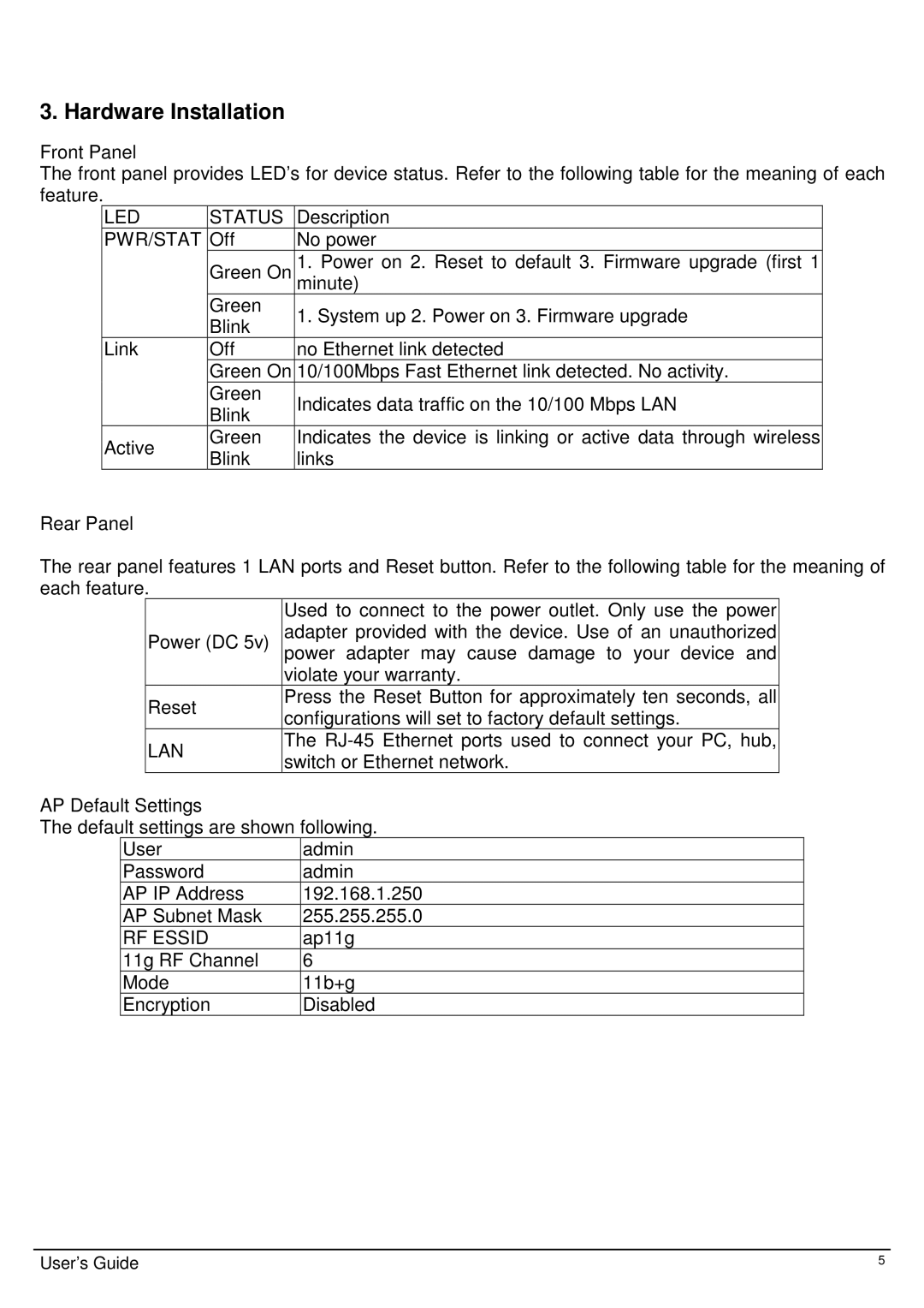
The front panel provides LED’s for device status. Refer to the following table for the meaning of each feature.
LED | STATUS | Description | |
PWR/STAT | Off | No power | |
| Green On | 1. Power on 2. Reset to default 3. Firmware upgrade (first 1 | |
|
| minute) | |
| Green | 1. System up 2. Power on 3. Firmware upgrade | |
| Blink | ||
|
| ||
Link | Off | no Ethernet link detected | |
| Green On | 10/100Mbps Fast Ethernet link detected. No activity. | |
| Green | Indicates data traffic on the 10/100 Mbps LAN | |
| Blink | ||
|
| ||
Active | Green | Indicates the device is linking or active data through wireless | |
Blink | links | ||
|
Rear Panel
The rear panel features 1 LAN ports and Reset button. Refer to the following table for the meaning of each feature.
| Used to connect to the power outlet. Only use the power | |
Power (DC 5v) | adapter provided with the device. Use of an unauthorized | |
| power adapter may cause damage to your device and | |
| violate your warranty. | |
Reset | Press the Reset Button for approximately ten seconds, all | |
configurations will set to factory default settings. | ||
| ||
LAN | The | |
switch or Ethernet network. | ||
|
AP Default Settings
The default settings are shown following.
User | admin |
Password | admin |
AP IP Address | 192.168.1.250 |
AP Subnet Mask | 255.255.255.0 |
RF ESSID | ap11g |
11g RF Channel | 6 |
Mode | 11b+g |
Encryption | Disabled |
User’s Guide | 5 |
