System Requirements
The following are basic requirements for using the Touch Monitor. Please check the specifications and Supported Video Timing section of this Users Guide for specifics.
∙This touch monitor requires connection to a personal computer. Both industry standard architecture and Macintosh hardware is supported.
∙Various Operating System versions are supported for touch input operation. Please check the product features and specifications to insure that the OS you intend to use is supported. The included software installation disc contains the proper drivers for supported Operating Systems and devices.
∙An analog, VESA standard video card for the PC is required. This touch monitor complies with DPMS and Plug & Play (DDC) standards.
∙The personal computer will require either a standard 9 pin serial COM port or USB port, depending on the product version of the touch monitor. If the serial COM port is a 25 pin,
∙There should be enough electrical outlets to support the system installation. This would include the calculation of total current requirements. Although not a strict requirement, a surge protected power source is recommended.
Mounting
The Touch Monitor may be used on any work surface by placing it on its supplied stand.
In addition, this product is provided with permanent mounting capabilities. The rear of the main display body has mounting holes configured to conform to the VESA mounting standard. Typically, this mounting pattern allows the Touch Monitor to be installed on movable arms and specialized mobile equipment.
Alternatively, there are slotted mounting holes on the bottom of the product pedestal which will facilitate permanent installation of this product to walls, countertops and custom installations. Typically, this mounting pattern is used to attach the Touch Monitor to a counter in a permanent position. This mounting scheme may provide the most secure and stable mounting environment.
Using any mounting method, consideration should be given to placement relative to cable length, power sources and cable routing.
Using Touch Input
The surface of this LCD Touch Monitor is a touch sensor. Some degree of caution is required to insure the effectiveness and long life as an input device. Avoid using sharp objects such as pens, pencils, scissors or screwdrivers as a pointing stylus. After installation of the driver software, a calibration should be performed. This action insures that the graphic coordinates match the touch coordinates, sometimes called mapping.
Different software applications may require specific “mouse click” parameters. The touch control panel will allow selection of multiple types of mouse button actions.
2
INSTALLING THE TOUCH MONITOR
•DO NOT install the monitor in areas where sudden temperature changes may occur, or in humid, dusty, or smoky environments as it may cause fire, electric shock or damage.
•DO NOT expose this product to rain, water, moisture, or sunlight
•MAINTAIN good ventilation; covering of ventilation slots or holes may cause a fire
•PLACE the monitor at least 4” (or 10 cm) way from the walls
•SAFE storage temperature of the LCD Touch Monitor is in a range of
•INSTALL the software drivers via the supplied CD following standard operating system procedures
NOTE
Remember that the connection of USB devices is done after the software drivers are loaded. Further instructions are provided during software installat ion and through the Help files on the driver CD.
Connecting the Monitor
1.Turn off the PC and the LCD Touch Monitor before making any connections.
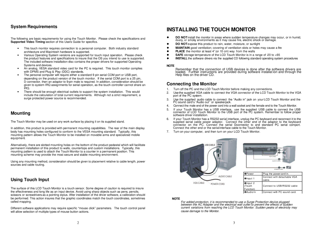
2.Use the supplied VGA cable to connect the VGA connector of the LCD Touch Monitor to the VGA port of the PC system.
3.Use the supplied audio cable to connect the “Audio in” jack on your LCD Touch Monitor and the PC sound card’s “Audio out” or speakerjack.
4.Connect the male end of the power cord into a wall socket and the female end to the Touch Monitor.
5.If your Touch Monitor has a USB interface, use the supplied USB cable to connect the USB connector of LCD Touch Monitor to the USB port of the PC system. Remember to follow proper software driver installation.
6.If your Touch Monitor has a RS232 serial interface, unplug the PC keyboard and reconnect it to the supplied serial cable power adaptor. Connect the other end of the adaptor to the keyboard connector on the PC. Connect the serial
7.Turn on your computer, and then turn on your LCD Touch Monitor.
uPower | Plug the power cord in. | |
vInput 1 | Connect with detachable VGA | |
cable. | ||
| ||
wInput 2 |
| |
(Touch | Connect to USB/RS232 cable | |
Function) |
| |
xAudio In | Connect with PC sound card. |
NOTE
For added protection, it is recommended to use a Surge Protection device plugged between the AC Adapter and the electrical wall outlet to prevent the effects of sudden
current variations from reaching the LCD Touch Monitor. Sudden peaks of electricity may cause damage to the Monitor.
3