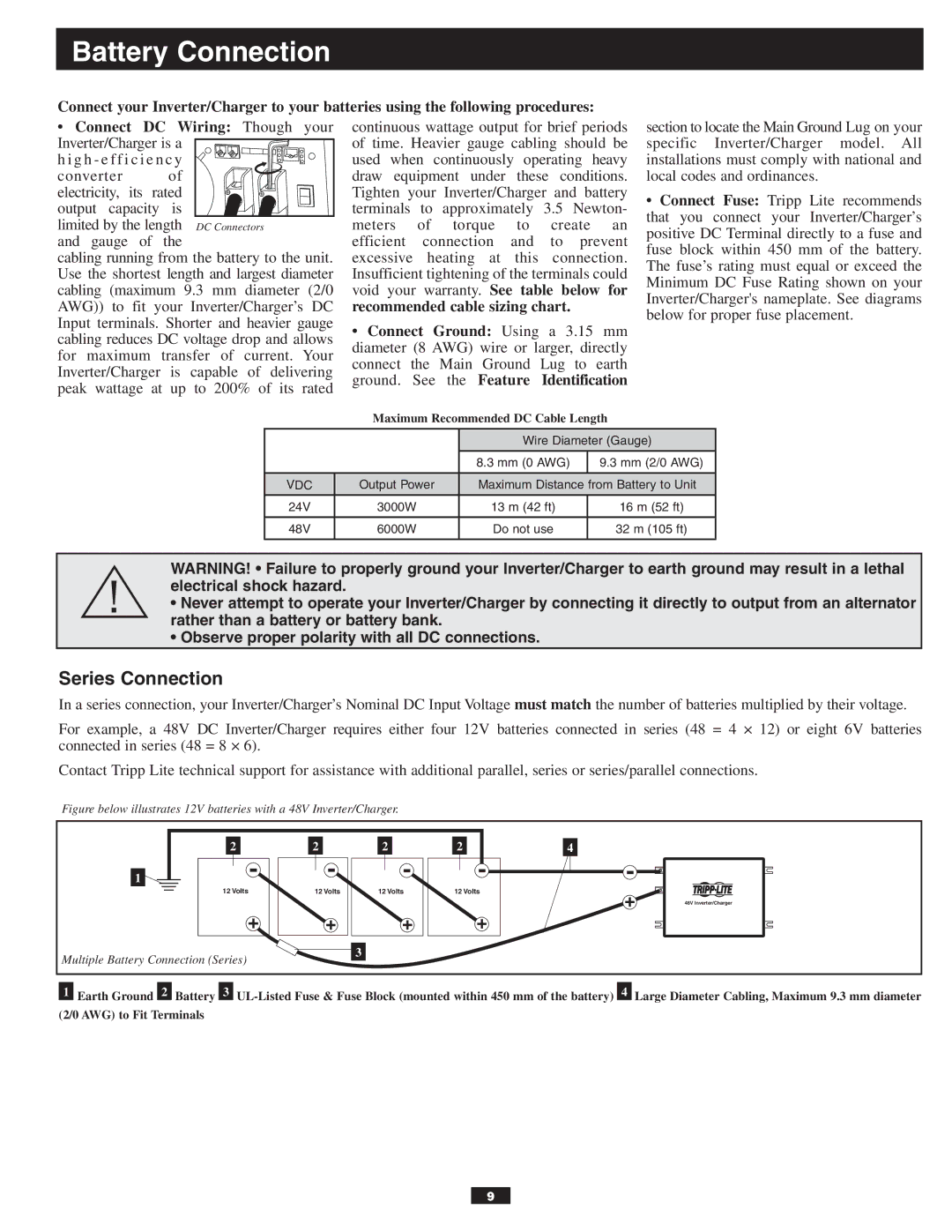
APSX6048VR specifications
The Tripp Lite APSX6048VR is a leading-edge power inverter designed to meet the diverse needs of users requiring reliable and efficient backup power solutions. With a robust AC output, this 6000-watt inverter provides the capability to power multiple devices and systems simultaneously, making it ideal for both residential and commercial use. Its high power capacity allows it to handle heavy loads, making it suitable for essential appliances, tools, and equipment.One of the standout features of the APSX6048VR is its advanced pure sine wave output. Unlike modified sine wave inverters, pure sine wave inverters deliver a smooth and consistent power supply that is compatible with sensitive electronics. This ensures safe and efficient operation for devices such as computers, medical equipment, and audio/visual systems, preventing damage and prolonging their lifespan.
The inverter also includes an impressive voltage output range of 48V, which optimizes performance and maximizes efficiency. This makes it an excellent choice for solar and battery backup systems, allowing for seamless integration with renewable energy setups. The APSX6048VR supports various charging input sources, making it versatile for different installations, whether on-grid or off-grid.
Another notable characteristic of this inverter is its built-in automatic transfer switch (ATS). This feature ensures a quick transition from mains power to inverter power in the event of a power failure, providing uninterrupted power to critical loads. Additionally, the Tripp Lite APSX6048VR features multiple safety mechanisms, including over-voltage protection, under-voltage protection, and short-circuit protection, guaranteeing safe operation under varying conditions.
The inverter is designed for easy installation and user-friendly operation. It comes equipped with an LCD display that provides vital system information such as input/output voltage, load capacity, and battery status. This real-time feedback allows users to monitor their power usage effectively.
With durable construction and a compact design, the Tripp Lite APSX6048VR is both portable and durable, making it a reliable choice for temporary setups or permanent installations. It’s an ideal power solution for anyone seeking a reliable inverter that combines high performance with advanced technology, ensuring that devices remain powered in any situation.

