B004-2DUA2-K, B004-2DUA4-K specifications
Tripp Lite, a leader in power management solutions and connectivity, offers a range of high-quality KVM switches ideal for managing multiple computers using a single keyboard, monitor, and mouse. Among their notable offerings are the Tripp Lite B004-2DUA4-K and B004-2DUA2-K models, designed to enhance productivity and streamline workspace management.The Tripp Lite B004-2DUA4-K is a 4-port USB KVM switch that supports high-definition video at resolutions up to 2048 x 1152, making it an excellent choice for users who require exceptional image quality. This KVM switch allows seamless switching between four connected computers using a single set of peripherals, allowing for efficient multitasking without the clutter of multiple keyboards and mice. It also includes built-in audio support, enabling users to switch between audio sources along with video, making it perfect for applications that require sound.
On the other hand, the B004-2DUA2-K model is a 2-port USB KVM switch, providing similar functionalities for those with fewer machines to manage. It supports resolutions up to 1920 x 1200, providing clear visuals tailored for common office tasks and multimedia consumption. Both models utilize USB 2.0 technology, ensuring fast and reliable data transmissions between the connected devices. They are compatible with a wide range of operating systems, including Windows, Linux, and macOS, making them incredibly versatile.
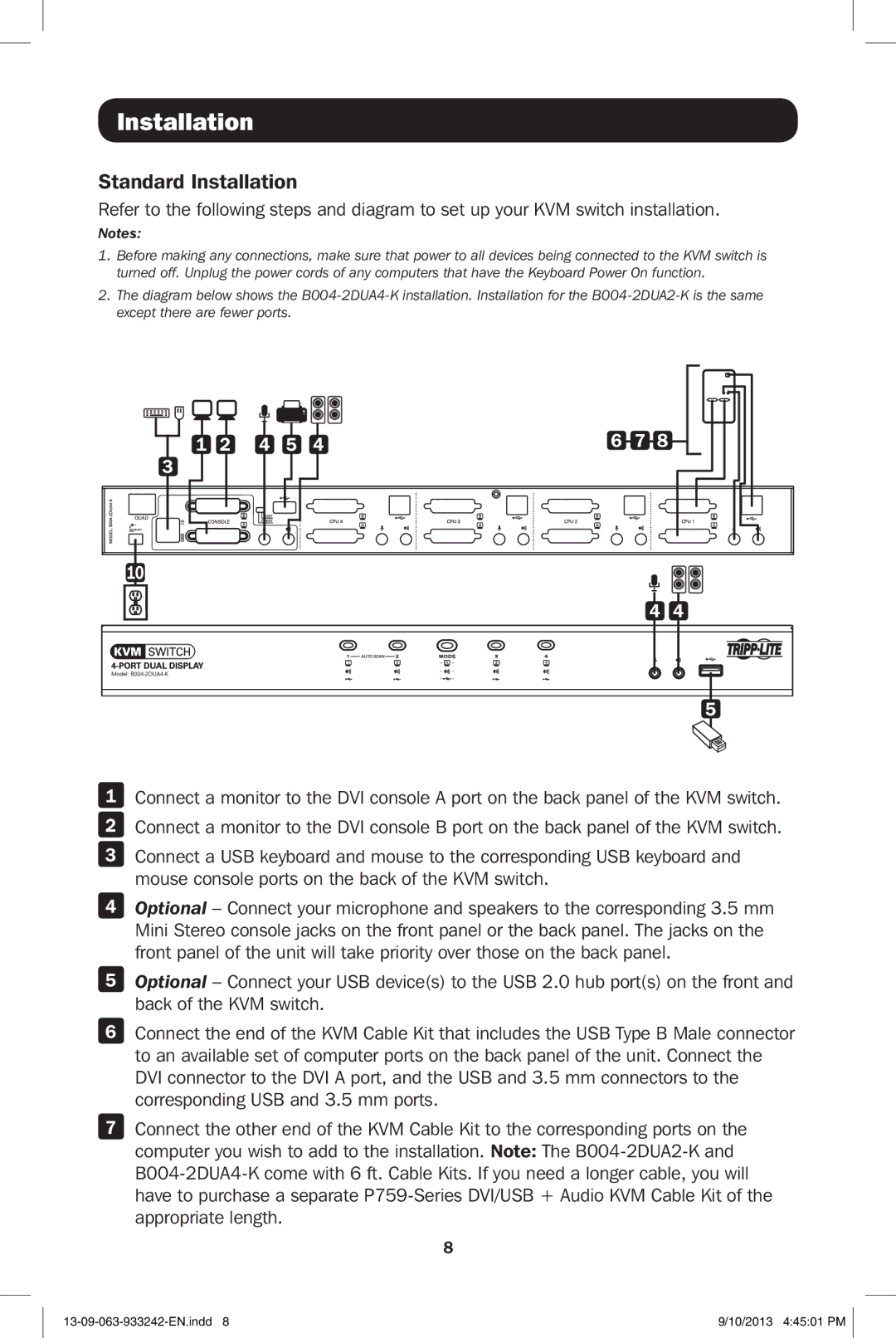
One of the standout features of both the B004-2DUA4-K and B004-2DUA2-K KVM switches is the easy installation process. Users can connect their computers and peripherals without the need for additional software. Included with the switches are all necessary cables, simplifying the setup procedure even further.
Additionally, these KVM switches are designed with durability in mind, featuring robust housing that can withstand the rigors of daily use. They employ hotkey switching capabilities which allow users to effortlessly switch between systems using keyboard shortcuts, making the transition smooth and user-friendly.
In summary, the Tripp Lite B004-2DUA4-K and B004-2DUA2-K KVM switches represent excellent solutions for anyone seeking efficient multi-computer management. With their combination of high-resolution support, ease of use, and compatibility across various platforms, they cater to both business and personal needs, making them a valuable addition to any workspace.

