1.Features (continued)
1.5External Views
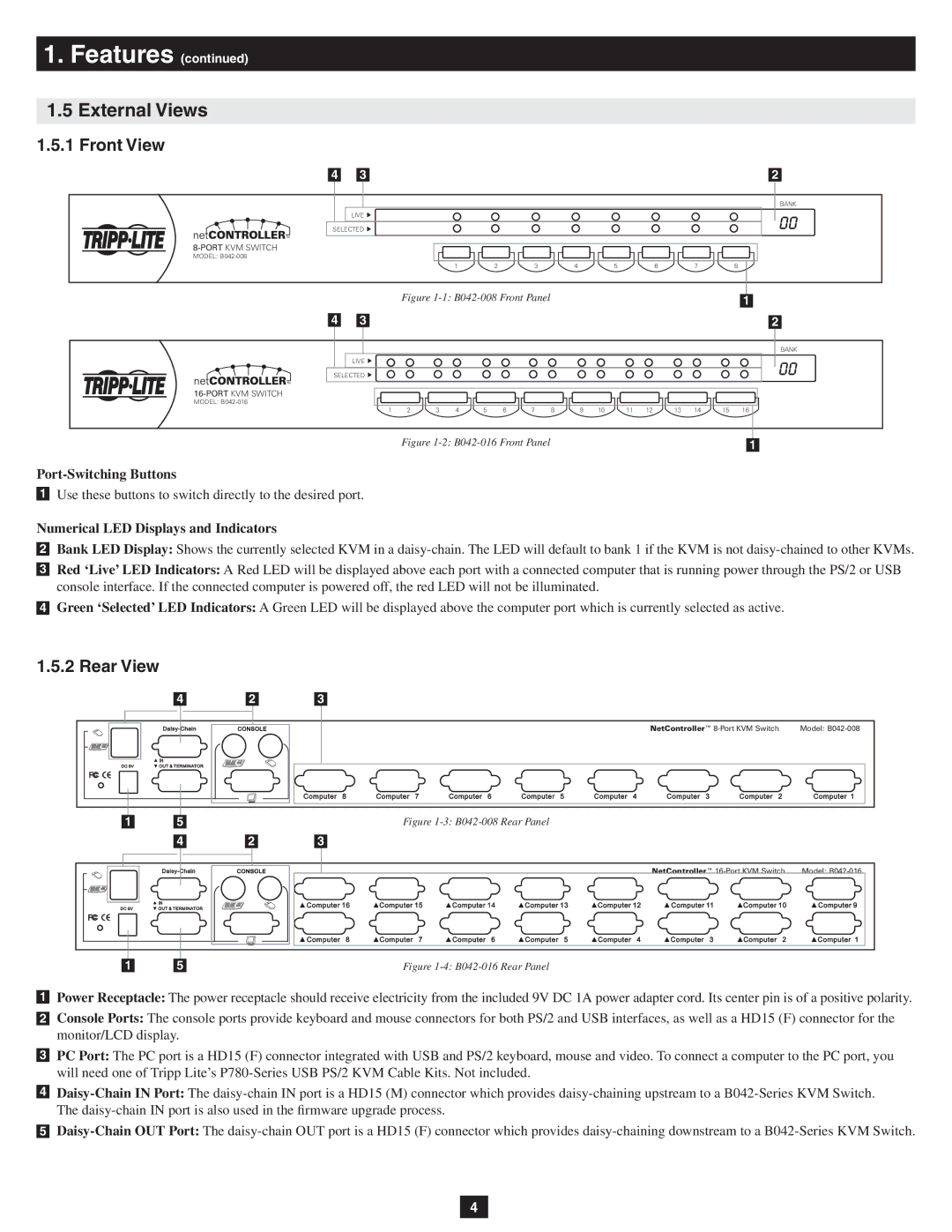
1.5.1 Front View
4 |
| 3 |
| 2 |
LIVE ![]()
SELECTED ![]()
MODEL:
1 | 2 | 3 | 4 | 5 | 6 | 7 | 8 |
BANK
|
|
| Figure |
|
|
|
|
|
| 1 |
|
| |
|
|
|
|
|
|
|
4 |
|
|
| |||
3 |
|
|
| 2 | ||
|
|
|
|
|
|
|
LIVE ![]()
SELECTED ![]()
MODEL:
1 | 2 | 3 | 4 | 5 | 6 | 7 | 8 | 9 | 10 | 11 | 12 | 13 | 14 | 15 | 16 |
BANK
Figure |
|
1 |
Port-Switching Buttons
1Use these buttons to switch directly to the desired port.
Numerical LED Displays and Indicators
2Bank LED Display: Shows the currently selected KVM in a
3Red ‘Live’ LED Indicators: A Red LED will be displayed above each port with a connected computer that is running power through the PS/2 or USB console interface. If the connected computer is powered off, the red LED will not be illuminated.
4Green ‘Selected’ LED Indicators: A Green LED will be displayed above the computer port which is currently selected as active.
1.5.2 Rear View
4 2 3
| NetController™ | Model: |
|
|
|
|
|
|
|
|
|
|
|
|
|
|
1 | 5 |
|
|
|
| Figure | |
|
|
|
|
|
|
|
|
| 4 | 2 | 3 |
|
NetController™ | Model: |
|
|
|
|
|
|
|
|
|
|
|
|
|
|
|
|
| 1 |
| 5 |
| Figure | ||
1Power Receptacle: The power receptacle should receive electricity from the included 9V DC 1A power adapter cord. Its center pin is of a positive polarity.
2Console Ports: The console ports provide keyboard and mouse connectors for both PS/2 and USB interfaces, as well as a HD15 (F) connector for the monitor/LCD display.
3PC Port: The PC port is a HD15 (F) connector integrated with USB and PS/2 keyboard, mouse and video. To connect a computer to the PC port, you will need one of Tripp Lite’s
4
5
4