3 • CONTROLS
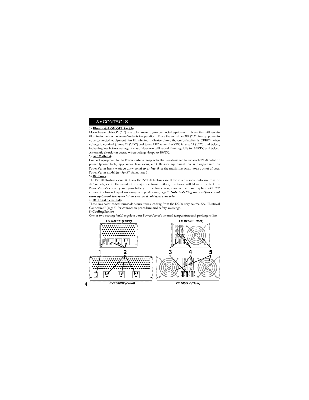
1)Illuminated ON/OFF Switch:
Move the switch to ON (“I”) to supply power to your connected equipment. This switch will remain illuminated while the PowerVerter is in operation. Move the switch to OFF (“O”) to stop power to your connected equipment. An illuminated indicator above the on/off switch is GREEN when voltage is nominal (above 11.8VDC) and turns RED when the VDC falls to 11.8VDC and below, indicating low battery voltage. An audible alarm will sound if voltage falls to 10.8VDC and below. Automatic shutdown occurs when voltage drops to 10VDC.
2)AC Outlet(s):
Connect equipment to the PowerVerter's receptacles that are designed to run on 120V AC electric power (power tools, appliances, televisions, etc.). Be sure equipment that is plugged into the PowerVerter has a wattage draw equal to or less than the maximum continuous output of your PowerVerter model (see Specifications, page 8).
3)DC Fuses:
The PV 1000 features four DC fuses; the PV 1800 features six. If too much current is drawn from the AC outlets, or in the event of a major electronic failure, the fuses will blow to protect the PowerVerter's circuitry and your battery. If the fuses blow, remove them and replace with 32V automotive fuses of equal amperage (see Specifications, page 8). Note: installing nonrated fuses could
cause equipment damage or failure and could void your warranty.
4)DC Input Terminals:
These two
5)Cooling Fan(s):
One or two cooling fan(s) regulate your PowerVerter's internal temperature and prolong its life.
PV 1000HF (Front)
1 | 2 |
PV 1000HF (Rear)
3 | 4 | 5 |
4 |
|
|
|
|
PV 1800HF (Front) | PV 1800HF (Rear) | |||
|
|
|
| |