Safety
Important Safety Instructions! Save These Instructions!
This manual contains important instructions and warnings that should be followed during the installation, operation and storage of all Tripp Lite Inverters.
Warning!
•Do not use a Tripp Lite PowerVerter Inverter in life support or healthcare applications where a malfunction or failure of a Tripp Lite PowerVerter Inverter could cause failure or significantly alter the performance of a life support device or medical equipment.
•Do not operate your Inverter near flammable materials, fumes or gases.
Caution!
•Since the Inverter requires adequate ventilation during operation, do not block fan or cooling vents or cover the Inverter, and do not operate near vehicle heating vents or in direct sunlight. Keep the Inverter dry at all times and disconnect when not in use.
•Since the Inverter case will get hot (55° - 60° C) during continuous extended use, use care when handling it. Do not place it near surfaces or materials affected by this level of heat.
•Turn OFF connected equipment before starting your engine. DO NOT plug a surge suppressor, line conditioner or UPS system into the Inverter. If you attach AC extension cords, use 18 AWG or
•Before connecting a battery charger or adapter, check its manual to make sure that the Inverter’s specifications (including output waveform) fall within its recommendations. Most battery chargers and adapters, however, are safe for connection, as long as their labels state that their
Operation
Step 1: Plug Inverter into vehicle lighter/accessory outlet.
Step 2: Turn on Inverter.
Step 3: Plug equipment into the Inverter.
Determine your equipment’s total wattage.* Do not connect more watts than your Inverter’s Output Power (Maximum Continuous Watts)
*Wattage ratings are usually listed in equipment manuals or on nameplates. If your equipment is rated in amps, multiply that number times AC utility voltage to determine watts. (Example: a ¼ in. drill requires 1.25 amps. 230 volts × 1.25 amps = 290 watts.)
Maintenance & Service
Your Inverter requires no maintenance and contains no
Feature Identification
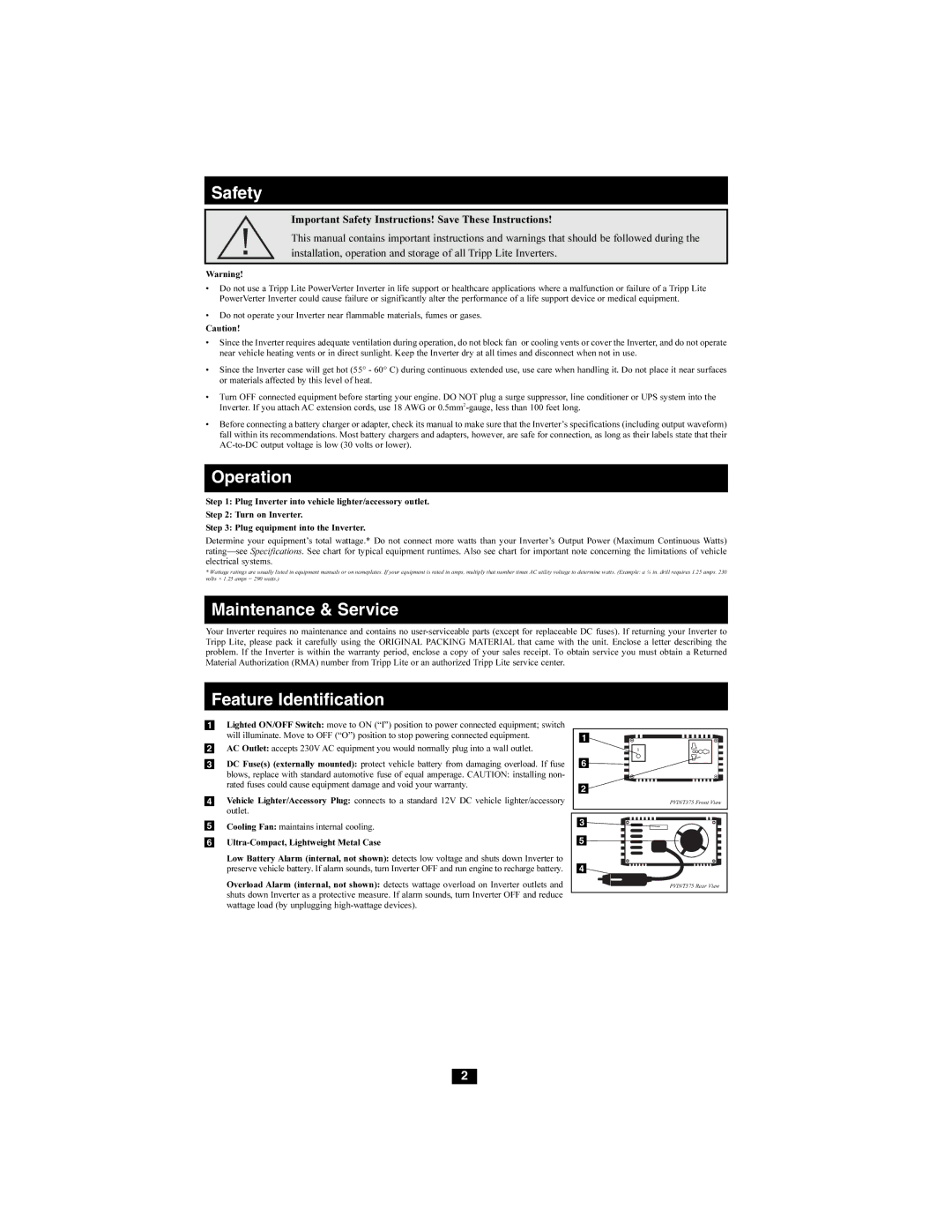
1Lighted ON/OFF Switch: move to ON (“I”) position to power connected equipment; switch will illuminate. Move to OFF (“O”) position to stop powering connected equipment.
2AC Outlet: accepts 230V AC equipment you would normally plug into a wall outlet.
3DC Fuse(s) (externally mounted): protect vehicle battery from damaging overload. If fuse
blows, replace with standard automotive fuse of equal amperage. CAUTION: installing non- rated fuses could cause equipment damage and void your warranty.
4Vehicle Lighter/Accessory Plug: connects to a standard 12V DC vehicle lighter/accessory outlet.
5Cooling Fan: maintains internal cooling.
6
Low Battery Alarm (internal, not shown): detects low voltage and shuts down Inverter to preserve vehicle battery. If alarm sounds, turn Inverter OFF and run engine to recharge battery.
Overload Alarm (internal, not shown): detects wattage overload on Inverter outlets and shuts down Inverter as a protective measure. If alarm sounds, turn Inverter OFF and reduce wattage load (by unplugging
1
6
2 |
PVINT375 Front View
3 |
5 |
4 |
PVINT375 Rear View |
2