Power Module Replacement

Power Module Replacement

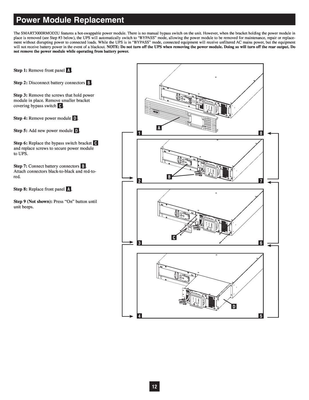
The SMART3000RMOD2U features a hot-swappable power module. There is no manual bypass switch on the unit. However, when the bracket holding the power module in place is removed (see Step #3 below), the UPS will automatically switch to “BYPASS” mode, allowing the power module to be removed for maintenance, repair or replace- ment without disrupting power to connected loads. While the UPS is in “BYPASS” mode, connected equipment will receive unfiltered AC mains power, but the equipment will not receive battery power in the event of a blackout. NOTE: Do not turn off the UPS when removing the power module. Doing so will turn off the rear output. Do not remove the power module while operating from battery power.

Step 1: Remove front panel A .

Step 2: Disconnect battery connectors B .

Step 3: Remove the screws that hold power module in place. Remove smaller bracket covering bypass switch C .

Step 4: Remove power module D .

Step 5: Add new power module D .

Step 6: Replace the bypass switch bracket C and replace screws to secure power module to UPS.

Step 7: Connect battery connectors B . Attach connectors black-to-black and red-to- red.

Step 8: Replace front panel A .

Step 9 (Not shown): Press “On” button until unit beeps.


A

1

8

2

B

7


C

3

6


D

4

5

12

Page 12
Image 12
Tripp Lite SMART3000RMOD2U owner manual Power Module Replacement, Not shown Press “On” button until unit beeps