Installation continued
Connecting the PDU
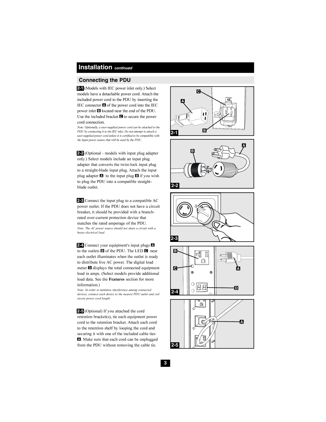
2-1(Models with IEC power inlet only.) Select models have a detachable power cord. Attach the included power cord to the PDU by inserting the
IEC connector A of the power cord into the IEC power inlet B located near the end of the PDU. Use the included bracket C to secure the power cord connection.
Note: Optionally, a user-supplied power cord can be attached to the PDU by connecting it to the IEC inlet. Do not attempt to attach a user-supplied power cord unless it is certified to be compatible with the input power source that will be used by the PDU.
2-2(Optional - models with input plug adapter only.) Select models include an input plug adapter that converts the twist-lock input plug to a straight-blade input plug. Attach the input plug adapter A to the input plug B if you wish to plug the PDU into a compatible straight- blade outlet.
2-3Connect the input plug to a compatible AC power outlet. If the PDU does not have a circuit breaker, it should be provided with a branch- rated over-current protection device that matches the rated amperage of the PDU.
Note: The AC power source should not share a circuit with a heavy electrical load.
2-4Connect your equipment's input plugs A to the outlets B of the PDU. The LED C near each outlet illuminates when the outlet is ready to distribute live AC power. The digital load meter D displays the total connected equipment load in amps. (Select models provide additional load data. See the Features section for more information.)
Note: In order to minimize interference among connected devices, connect each device to the nearest PDU outlet and coil excess power cord length.
2-5(Optional) If you attached the cord retention bracket(s), tie each equipment power cord to the retention bracket. Attach each cord to the retention shelf by looping the cord and securing it with one of the included cable ties A . Make sure that each cord can be unplugged
from the PDU without removing the cable tie.

