ASSEMBLY STEP
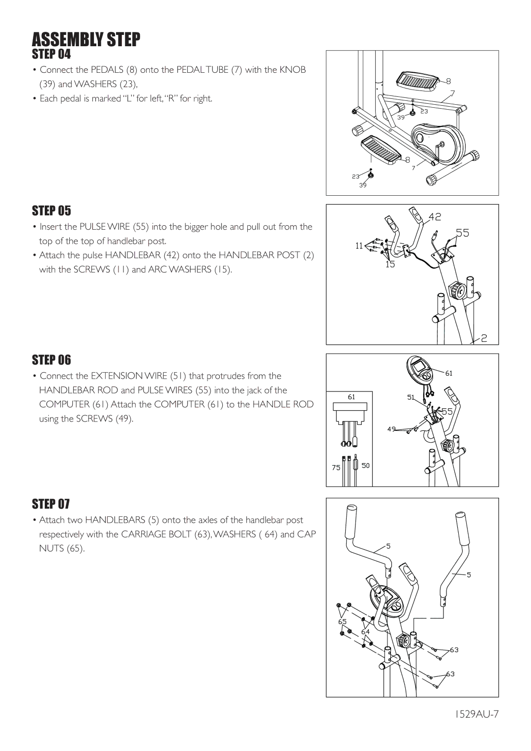
STEP 04
•Connect the PEDALS (8) onto the PEDAL TUBE (7) with the KNOB
(39)and WASHERS (23),
•Each pedal is marked “L” for left, “R” for right.
STEP 05
•Insert the PULSE WIRE (55) into the bigger hole and pull out from the top of the top of handlebar post.
•Attach the pulse HANDLEBAR (42) onto the HANDLEBAR POST (2) with the SCREWS (11) and ARC WASHERS (15).
STEP 06
•Connect the EXTENSION WIRE (51) that protrudes from the HANDLEBAR ROD and PULSE WIRES (55) into the jack of the COMPUTER (61) Attach the COMPUTER (61) to the HANDLE ROD using the SCREWS (49).
STEP 07
•Attach two HANDLEBARS (5) onto the axles of the handlebar post respectively with the CARRIAGE BOLT (63), WASHERS ( 64) and CAP NUTS (65).