| Section 5: Maintenance | 13 |
|
|
|
|
|
|
WARNING
Before inspecting, cleaning or servicing the machine, shut off engine, wait for all moving parts to come to a stop, disconnect spark plug wire and move wire away from spark plug. Remove key on electric start models.
Failure to follow these instructions can result in serious personal injury or property damage.
11.Using a 9/16" wrench and a 7/32" hex (Allen) wrench, loosen the mounting nut (G, Figure
(J). Remove belt.
12.Loosen rear belt guide screw (K, Figure
Belt Replacement
1. Install belt on engine pulley (L, Figure |
(K) securely. |
2. Route belt between idler pulley (I, |
Figure |
brake arm (M), and next to |
guides (N). |
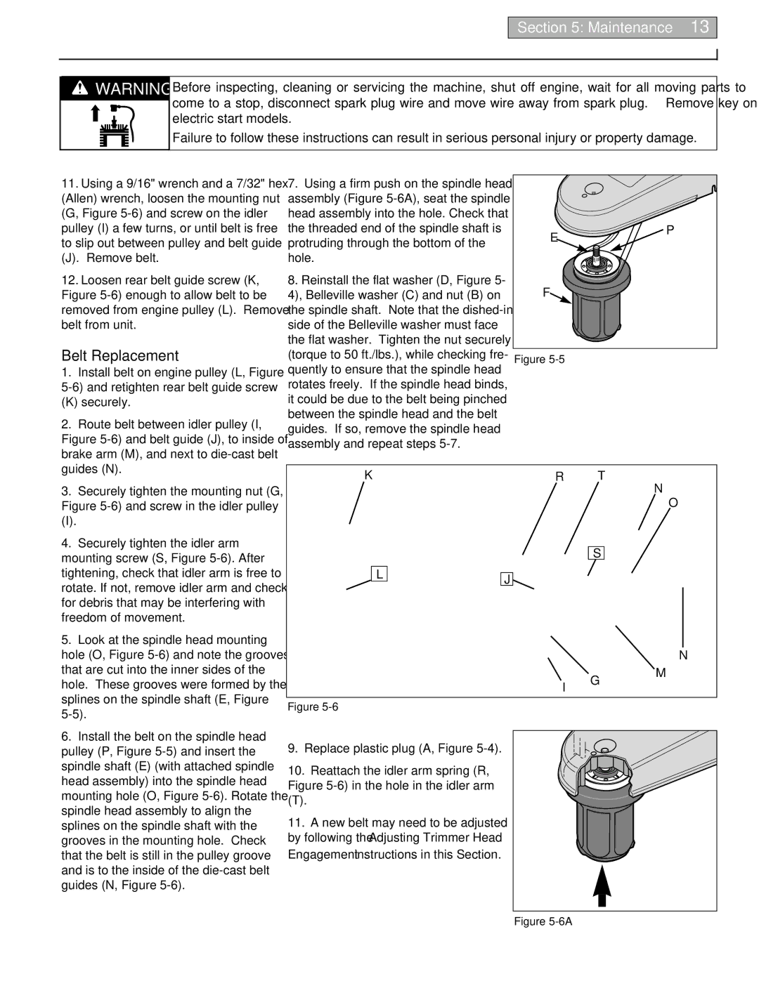
7.Using a firm push on the spindle head assembly (Figure
8.Reinstall the flat washer (D, Figure 5- 4), Belleville washer (C) and nut (B) on the spindle shaft. Note that the
E | P |
| |
F |
|
Figure |
|
3. | Securely tighten the mounting nut (G, |
Figure | |
(I). |
|
4. | Securely tighten the idler arm |
mounting screw (S, Figure | |
KR T
N
O
S
tightening, check that idler arm is free to |
rotate. If not, remove idler arm and check |
for debris that may be interfering with |
freedom of movement. |
5. Look at the spindle head mounting |
hole (O, Figure |
that are cut into the inner sides of the |
hole. These grooves were formed by the |
splines on the spindle shaft (E, Figure |
6. Install the belt on the spindle head |
pulley (P, Figure |
spindle shaft (E) (with attached spindle |
head assembly) into the spindle head |
mounting hole (O, Figure |
spindle head assembly to align the |
splines on the spindle shaft with the |
grooves in the mounting hole. Check |
that the belt is still in the pulley groove |
and is to the inside of the |
guides (N, Figure |
L | J |
|
I G
Figure
9. Replace plastic plug (A, Figure 5-4).
10. Reattach the idler arm spring (R, Figure
(T).
11.A new belt may need to be adjusted by following the Adjusting Trimmer Head Engagement instructions in this Section.
N
M