I]
Assembly
WARNING
To prevent personal injury or property damage, do not start the engine until all assembly steps are complete and you have read and understand the
safety and operating instruc- tions in this manual.
Introduction
Carefullyfollow theseassembly steps to correctly prepareyour tiller for use. It is recommended that you readthis Section in its entirety before beginning assembly. NOTE: Enginesyles vary by model. The engineon your tiller may appeardiffer- ently than those shown in illustrations and Figuresthroughout this manual.
Inspect unit
Inspect the unit and carton for damage immediately after delivery. Contactthe carrier (trucking company) if you find or suspect damage. Inform them of the damageand request instructions for filing aclaim. To protect your rights, put your claim in writing and mail a copy to the
carrier within 15 daysafter the unit has beendelivered.
STEP1: UnpackingInstructions
1.Removeany cardboard inserts and packagingmaterial from the carton. Removeany staples from the bottom of the carton and then lift the carton up and off the unit.
2.The tiller is heavyandyou should not attempt to remove it from the shipping platform until the handlebarsare installed. The procedure for removing the tiller is explained in Step 3 of these assembly steps.
NOTE:Becareful not to severely bendany of the control cables on the unit.
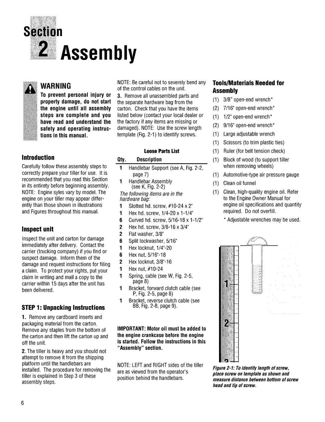
3.Removeall unassembled parts and the separatehardware bag from the carton. Checkthat you havethe items listed below (contact your local dealer or the factory if any items are missing or damaged). NOTE: Usethe screw length template (Fig.
LooseParts List
Qty. Description
1HandlebarSupport (seeA, Fig.
1HandlebarAssembly (see K, Fig.
Thefollowing items are in the hardware bag:
1Slotted hd. screw,
1Hexhd. screw,
6Curvedhd. screw,
2Hexhd. screw,
2 Flatwasher, 3/8"
6Split Iockwasher,5/16"
1Hexlocknut,
6Hexnut,
2Hexlocknut,
1
1Spring, cable (see W, Fig.
1Bracket,forward clutch cable (see P, Fig.
1Bracket,reverseclutch cable (see BB, Fig.
IMPORTANT:Motor oil must be addedto
the engine crankcasebeforethe engine is started. Followthe instructionsin this
"Assembly" section.
NOTE:LEFTand RIGHTsides of the tiller
are as viewed from the operator's position behindthe handlebars.
Tools]MaterialsNeededfor Assembly
(1)3/8"
(2)7/16"
(1)ll2"
(2)9/16"
(1)Largeadjustable wrench
(1)Scissors (to trim plastic ties)
(1)Ruler (for belt tension check)
(1)Block of wood (to support tiller when removing wheels)
(1)
(1)Cleanoilfunnel
(1)
*Adjustablewrenches may beused.
Figure2-1: Toidentifylengthofscrew, placescrewontemplateas shownand measuredistancebetweenbottomof screw
headandtip ofscrew.
6