Troy-Bilt 644H manual Assembly, MoveTiller OffShipping Platform, Attach Handlebar

Models: 644H

1 36
Download 36 pages 18.6 Kb
Page 7
Image 7
STEP 2: Attach Handlebar

STEP 2: Attach Handlebar

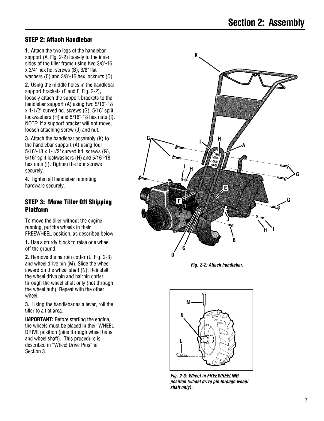
1.Attach the two legs of the handlebar support (A, Fig. 2-2) loosely to the inner sides of the tiller frame using two 3/8"-16 x 3/4" hex hd. screws (B), 3/8" flat washers (C) and 3/8"-16 hex Iocknuts (D).

2.Using the middle holes in the handlebar support brackets (Eand F,Fig. 2-2), loosely attach the support brackets to the handlebarsupport (A) using two 5/16"-18 x 1-1/2" curved hd. screws (G), 5/16" split Iockwashers (H) and 5/16"-18 hex nuts (I). NOTE:If a support bracket will not move, loosen attaching screw (J) and nut.

3.Attach the handlebarassembly (K) to the handlebarsupport (A) using four 5/16"-18 x 1-1/2" curved hd. screws (G), 5/16" split Iockwashers(H) and 5/16"-18 hex nuts (I). Tighten the four screws securely.

4.Tighten all handlebar mounting hardware securely.

STEP3: MoveTiller OffShipping Platform

To movethe tiller without the engine running, put the wheels in their FREEWHEELposition, as described below.

1.Usea sturdy block to raise onewheel off the ground.

2.Removethe hairpin cotter (L, Fig. 2-3) and wheel drive pin (M). Slide the wheel inward on the wheel shaft (N). Reinstall the wheel drive pin and hairpin cotter through the wheel shaft only (not through

the wheel hub). Repeatwith the other wheel.

3.Using the handlebaras a lever, roll the tiller to aflat area.

IMPORTANT:Before starting the engine, the wheels must be placed in their WHEEL DRIVEposition (pins through wheel hubs

and wheel shaft). This procedure is described in "Wheel Drive Pins" in

Section 3.

Section2: Assembly

\

B

C

D

Fig. 2-2: Attach handlebar.

I

L

Fig. 2-3: Wheel in FREEWHEELING position (wheel drive pin throughwheel shaRonly).

Page 7
Image 7
Troy-Bilt 644H manual Assembly, MoveTiller OffShipping Platform, Attach Handlebar