8Section 2: Assembly
CAUTION
Incorrect cable adjustment could cause the wheels and tines to rotate unexpect- edly. Follow adjustment procedures carefully. Failure to do so could result in personal injury or property damage.
4.Check for correct spring/cable tension as instructed in Section 5, Checking and Adjusting Forward Clutch Belt Tension.
5.When tension is correct, tighten the two jam nuts (B) securely.
STEP 5: CHECK TRANSMISSION GEAR OIL LEVEL
The transmission was filled with gear oil at the factory. However, be sure to check the oil level at this time to make certain it is correct.
IMPORTANT: Do not operate the tiller if the gear oil level is low. Doing so will result in severe damage to the transmis- sion components.
1.With the tiller on level ground, pull the Depth Regulator Lever (R, Figure
2.Remove the oil level check plug (M, Figure
M
Figure 2-10: Gear oil level check plug.
3.If oil does not flow from the check hole, add oil as follows:
NOTE: Do not use automatic transmission fluid or motor oil in the transmission.
(a)Clean area around the fill hole (N, Figure
N
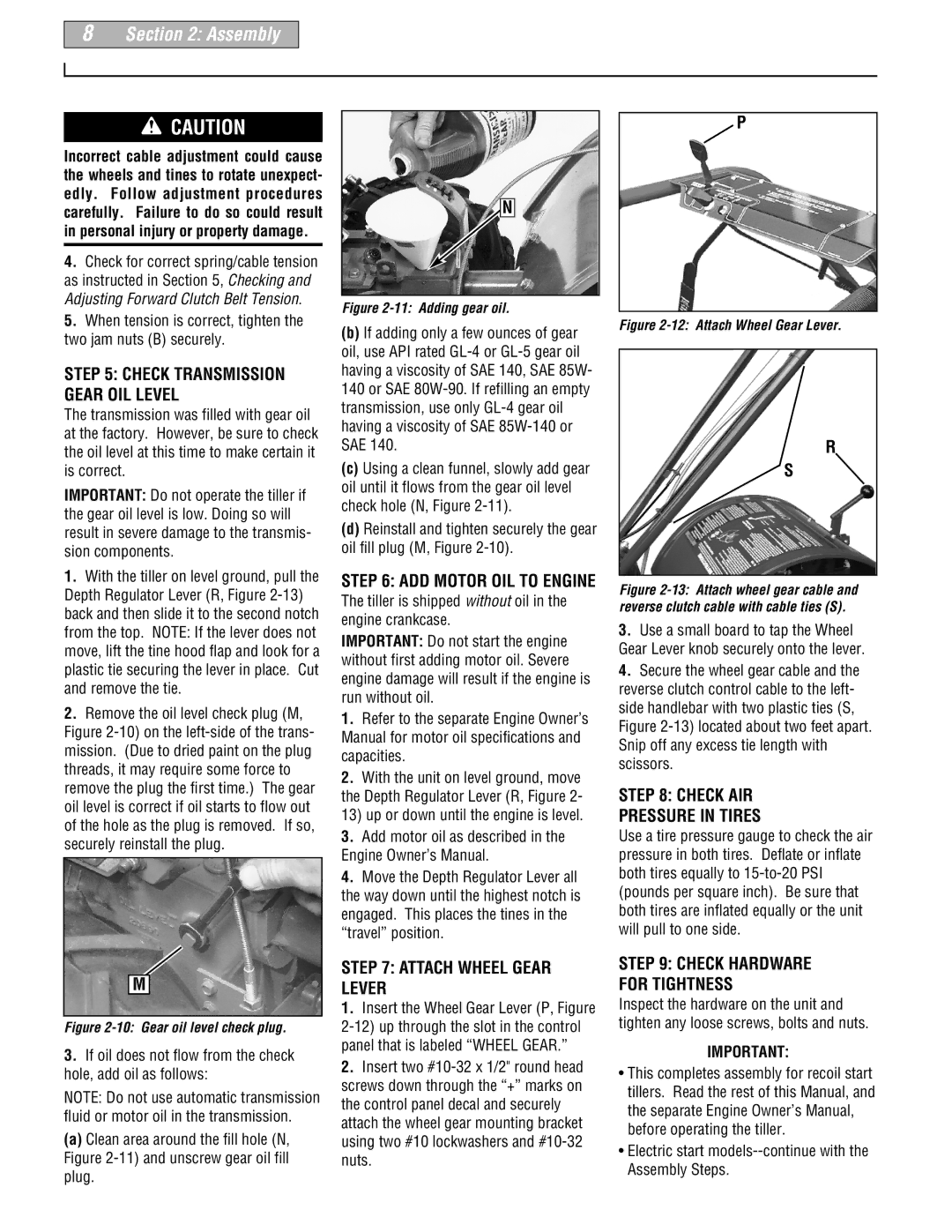
Figure 2-11: Adding gear oil.
(b)If adding only a few ounces of gear oil, use API rated
(c)Using a clean funnel, slowly add gear oil until it flows from the gear oil level check hole (N, Figure
(d)Reinstall and tighten securely the gear oil fill plug (M, Figure
STEP 6: ADD MOTOR OIL TO ENGINE
The tiller is shipped without oil in the engine crankcase.
IMPORTANT: Do not start the engine without first adding motor oil. Severe engine damage will result if the engine is run without oil.
1.Refer to the separate Engine Owner’s Manual for motor oil specifications and capacities.
2.With the unit on level ground, move the Depth Regulator Lever (R, Figure 2- 13) up or down until the engine is level.
3.Add motor oil as described in the Engine Owner’s Manual.
4.Move the Depth Regulator Lever all the way down until the highest notch is engaged. This places the tines in the “travel” position.
STEP 7: ATTACH WHEEL GEAR LEVER
1.Insert the Wheel Gear Lever (P, Figure
2.Insert two
P
Figure 2-12: Attach Wheel Gear Lever.
R
S
Figure 2-13: Attach wheel gear cable and reverse clutch cable with cable ties (S).
3.Use a small board to tap the Wheel Gear Lever knob securely onto the lever.
4.Secure the wheel gear cable and the reverse clutch control cable to the left- side handlebar with two plastic ties (S, Figure
STEP 8: CHECK AIR
PRESSURE IN TIRES
Use a tire pressure gauge to check the air pressure in both tires. Deflate or inflate both tires equally to
STEP 9: CHECK HARDWARE FOR TIGHTNESS
Inspect the hardware on the unit and tighten any loose screws, bolts and nuts.
IMPORTANT:
•This completes assembly for recoil start tillers. Read the rest of this Manual, and the separate Engine Owner’s Manual, before operating the tiller.