moving partsto come to a complete stop, disconnectspark plug wire and move wire awayfrom
,_ WARNING: Beforeinspecting, cleaning or servicing the machine,shut off engine, wait for all spark plug. Failureto follow these instructions can result in serious personal injury or property
damage.
ToCheckandAdjustTensiononthe Forward
|
|
|
|
|
|
|
| DriveBelt: | |
|
|
|
|
|
|
|
| 1. Checkingfor correct belttension is the | |
|
|
|
|
|
|
|
| sameas that described in item 5, Step 4: | |
|
|
|
|
|
|
|
| Attach Forward ClutchRod. Beforecheck- | |
|
|
|
|
| C |
|
| ing, shut off the engine, disconnect the | |
|
|
|
|
|
|
| spark plug wire, andallow the engineand | ||
|
|
|
|
|
|
| D | ||
|
|
|
| SHAFT |
|
| muffler to cool down. If, after following | ||
|
|
|
|
|
|
| |||
|
|
|
|
|
|
|
| the adjustment procedures, you cannot | |
|
|
|
|
|
|
|
| get the correct gap on the forward clutch | |
|
|
|
|
|
|
|
| rod adjustment bracket, you will needto | |
|
|
| ENGINE |
|
|
|
| makea secondary adjustment as de- | |
|
|
|
|
|
|
|
| scribed next. | |
|
|
|
|
|
|
|
| 2. Disconnectthe ForwardClutch Rod (A, | |
| I_ | OFENOTESTINE CUTTING EDGE I |
|
|
|
| Figure | ||
|
|
|
|
| removing the innermost hairpin cotter | ||||
|
|
|
|
|
|
|
| ||
|
|
|
|
|
|
|
| (C). | |
|
|
|
|
|
|
|
| 3. Unthreadthe Forward Clutch Rod (in a | |
|
| counterclockwise direction as viewed | |||||||
|
|
|
|
|
|
|
| from the front of the unit) until oneor two | |
|
|
|
|
|
|
|
| threads on the rod extendabovethe rect- | |
_b | _ | belt adjustment instructions | angular nut (D, | ||||||
| ARNING: | This is a CRT |
| ARNING: | Follow the | ward clutch bracket. | |||
| and its tines must be mounted |
| carefully. An incorrect | ||||||
|
| 4. Removethe belt cover. | |||||||
| in the direction shown in |
| adjustment could result in the | ||||||
|
|
| ForwardClutch mechanism | 5. Slip the forward drive belt (E, Figure | |||||
| could result in personal injury |
| engagingtoo soon. This could | ||||||
|
| he | |||||||
| or property damage. |
| causeloss of tiller control and | ||||||
|
| pushing it off (awayfrom engine) with | |||||||
|
|
|
|
| result in personal injury or | ||||
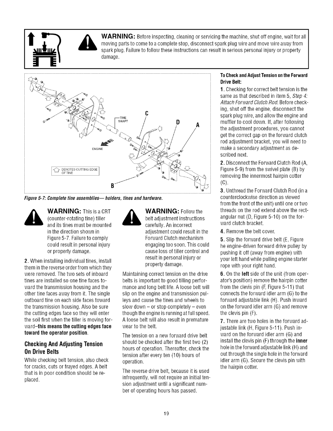
2. When installing individual tines, install |
| your left handwhile pulling enginestarter | |||||||
| property damage. | rope with your right hand. | |||||||
them inthe reverseorder from which they |
| ||||||||
|
|
|
| ||||||
|
|
|
|
| |||||
were removed.The two sets of inboard | Maintaining correct tension on the drive | 6. Onthe left side of the unit (from oper- | |||||||
tines are installed so one fine faces to- | belts is important to good tilling perfor- | ator'sposition) removethe hairpin cotter | |||||||
ward the transmission housing and the | manceand long belt life. A loose belt will | from the clevis pin (F,Figure | |||||||
other fine faces awayfrom it. The single | slip on the engine and transmission pul- | connectsthe forward idler arm (G)to the | |||||||
outboard tine on each side facestoward | leys and causethe tines and wheelsto | forward adjustable link (H). Push inward | |||||||
the transmission housing. Also be sure | slow down - | or stop completely - even | on the forward idler arm (G) and remove | ||||||
the cutting edges face so they will enter | though the engineis runningat full speed. | the clevis pin (F). | |||||||
the soil first when the tiller | is moving for- | A loose belt will also result in premature | 7. Thereare two holes in the forward ad- | ||||||
meansthe cuttingedgesface | wear to the belt. |
| justable link (H, | ||||||
toward the operator position. |
|
|
|
| |||||
Thetension on a new forward drive belt | ward on the forward idler arm (G) and | ||||||||
|
|
|
| ||||||
CheckingAndAdjustingTension | should be checkedafter the first two (2) | install the clevis pin (F)through the inner | |||||||
hours of operation. Thereafter,check the | holein the forward adjustablelink (H) and | ||||||||
On DriveBelts |
| ||||||||
| tension after every ten (10) hours of | out through the single hole in the forward | |||||||
While checking belt tension, also check | |||||||||
operation. |
|
|
| idler arm (G). Securethe clevis pin with | |||||
for cracks, cuts or frayed edges. A belt | The reversedrive belt, becauseit is used | the hairpin cotter. | |||||||
that is in poor condition should be re- |
| ||||||||
|
|
|
|
| |||||
placed. | infrequently, will not requirean initial ten- | |
sion adjustment until a significant num- | ||
| ||
| ber of operating hours has passed. |
19