Section 5: Maintenance

WARNING

Before inspecting, cleaning or servicing the machine, shut off engine, wait for all moving parts to come to a complete stop, disconnect spark plug wire and move wire away from spark plug. Remove ignition key, if so equipped.

Failure to follow these instructions can result in serious personal injury or property damage.

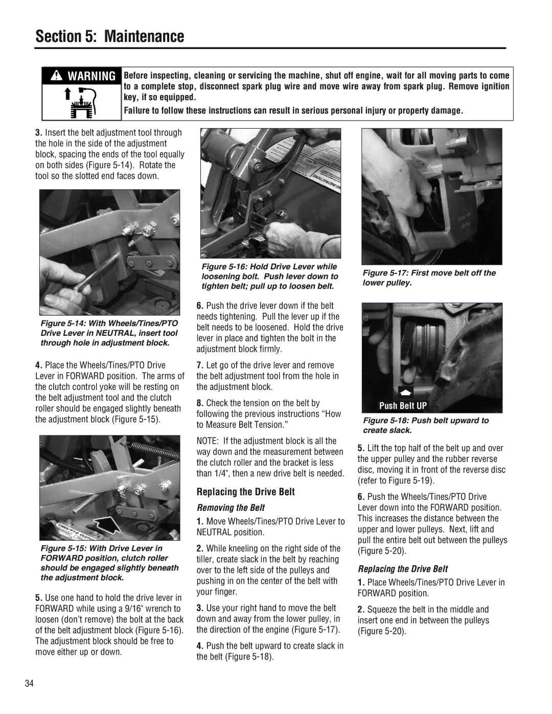
3.Insert the belt adjustment tool through the hole in the side of the adjustment block, spacing the ends of the tool equally on both sides (Figure 5-14). Rotate the tool so the slotted end faces down.

Figure 5-14: With Wheels/Tines/PTO Drive Lever in NEUTRAL, insert tool through hole in adjustment block.

4.Place the Wheels/Tines/PTO Drive Lever in FORWARD position. The arms of the clutch control yoke will be resting on the belt adjustment tool and the clutch roller should be engaged slightly beneath the adjustment block (Figure 5-15).

Figure 5-16: Hold Drive Lever while loosening bolt. Push lever down to tighten belt; pull up to loosen belt.

6.Push the drive lever down if the belt needs tightening. Pull the lever up if the belt needs to be loosened. Hold the drive lever in place and tighten the bolt in the adjustment block firmly.

7.Let go of the drive lever and remove the belt adjustment tool from the hole in the adjustment block.

8.Check the tension on the belt by following the previous instructions “How to Measure Belt Tension.”

Figure 5-17: First move belt off the lower pulley.

Push Belt UP

Figure 5-18: Push belt upward to create slack.

Figure 5-15: With Drive Lever in FORWARD position, clutch roller should be engaged slightly beneath the adjustment block.

5.Use one hand to hold the drive lever in FORWARD while using a 9/16" wrench to loosen (don’t remove) the bolt at the back of the belt adjustment block (Figure 5-16). The adjustment block should be free to move either up or down.

NOTE: If the adjustment block is all the way down and the measurement between the clutch roller and the bracket is less than 1/4", then a new drive belt is needed.

Replacing the Drive Belt

Removing the Belt

1.Move Wheels/Tines/PTO Drive Lever to NEUTRAL position.

2.While kneeling on the right side of the tiller, create slack in the belt by reaching over to the left side of the pulleys and pushing in on the center of the belt with your finger.

3.Use your right hand to move the belt down and away from the lower pulley, in the direction of the engine (Figure 5-17).

4.Push the belt upward to create slack in the belt (Figure 5-18).

5.Lift the top half of the belt up and over the upper pulley and the rubber reverse disc, moving it in front of the reverse disc (refer to Figure 5-19).

6.Push the Wheels/Tines/PTO Drive Lever down into the FORWARD position. This increases the distance between the upper and lower pulleys. Next, lift and pull the entire belt out between the pulleys (Figure 5-20).

Replacing the Drive Belt

1.Place Wheels/Tines/PTO Drive Lever in FORWARD position.

2.Squeeze the belt in the middle and insert one end in between the pulleys (Figure 5-20).

34

Page 34
Image 34
Troy-Bilt E686N, 682J, E682L manual Replacing the Drive Belt, Removing the Belt

E682L, E686N, 682J specifications

The Troy-Bilt E682L and E682J are two powerful and efficient snow throwers designed for residential use, enabling homeowners to tackle winter's toughest snow challenges with ease. Both models are part of Troy-Bilt's commitment to creating durable equipment that simplifies outdoor maintenance.

One of the main features of the Troy-Bilt E682L and E682J is their robust engine. Equipped with a reliable 243cc OHV (Overhead Valve) engine, these snow throwers provide robust power, ensuring that users can clear snow quickly and effectively. The engines are designed for easy starting, even in cold conditions, so you won’t have to worry about fumbling with difficult pull cords when snowy weather strikes.

Another significant characteristic of these models is their 24-inch clearing width combined with a 21-inch intake height. This allows for efficient snow removal, enabling users to clear driveways and sidewalks with fewer passes. The heavy-duty auger system is engineered to cut through packed snow with ease, ensuring that even the toughest winter weather conditions don’t stand a chance.

Both the E682L and E682J feature a 180-degree adjustable chute that directs the snow where it needs to go. This puts control in the hands of the user, preventing snow from being thrown back onto the paths that have already been cleared. The quick-release chute deflector allows for easy height adjustments, giving users the flexibility to adapt to different snow conditions.

These models are also designed with user comfort in mind. The Troy-Bilt E682L and E682J come with heated hand grips, which make operating the snow thrower more pleasant during long periods in cold weather. The ergonomic handles provide a comfortable grip, and the adjustable handle height ensures that users of various sizes can operate the machine comfortably.

Additionally, both models feature large, rugged tires that provide enhanced traction on various surfaces, whether it’s icy pavement or a snow-covered driveway. This design consideration contributes to their overall stability and maneuverability, allowing users to navigate through challenging winter conditions with confidence.

In summary, the Troy-Bilt E682L and E682J snow throwers are powerful, user-friendly machines equipped with essential features that make snow removal efficient and manageable. With their reliable engines, robust clearing capabilities, adjustable chutes, and comfortable handling, these models are valuable tools for any homeowner looking to stay ahead of winter weather.