Operator’s Manual
Table of Contents
Before cleaning, repairing, or
Safety Alert Symbol
Restrain the tiller
Safety
Tines/PTO Drive Lever into
All controls. Do not attempt to
Descriptions are used on the tiller and engine
Operating Symbols
Various symbols shown here, with word
Your unit may not have all of the symbols
Attach Handlebar
Tools/Materials Needed for Assembly
Introduction
Inspect Unit
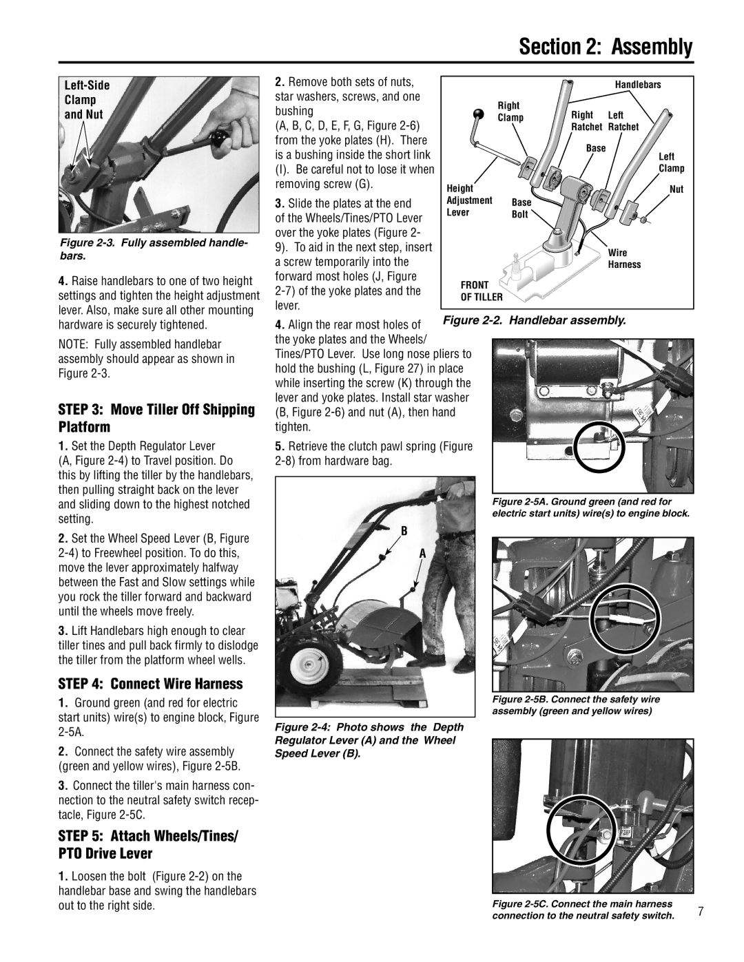
Left-Side Clamp Nut
Assembly
Connect Wire Harness
Move Tiller Off Shipping Platform
Remove the temporary screw J, Figure
Check Gear Oil Levels
Oil Level Hole
Adjust Air Pressure in Tires
Attach Engine Throttle Lever and Cable
Add Motor Oil to Engine
Never bring a gas can near the positive
Install Battery Cables
Connect the Wire Harness Receptacle
To Avoid Personal Injury or Property Damage
Engine
PTO Attachments Feature
Wheels/Tines/PTO Drive Lever
Forward Interlock Levers
Tines/PTO Clutch Lever
Features and Controls
Handlebar Height Adjustment Lever
Wheel Speed Lever
Engine Controls Engine Throttle Lever
Keyswitch Starter
Starting and Stopping the Engine
Following steps describe how to start and stop the engine
Pre-Start Checklist
Break-In Operation
Starting the Engine
Operation
Move engine throttle lever -2 away from Stop
Moving the Tiller Forward and Tilling
Cold Weather Operation
Operating the Tiller
Stopping the Engine and Tiller
Making Turns
Moving the Tiller in Reverse
Stopping Reverse Motion
To Stop the Engine
Transporting The Tiller Around Your Property
Testing the Forward Interlock Safety System
How to Check the Interlock System
Loading and Unloading the Tiller
Changing Belt From LOW Range to High Range
Changing Speed Belts
Loading the Tiller
Unloading the Tiller
Go to right side of tiller and finish seating the belt
Choosing Wheel Tine Speeds
Changing Belt From High Range to LOW Range
Move the Wheels/Tines/PTO Drive Lever into Neutral
To help avoid personal injury, be aware
Let the tiller do the work
Tilling depths
Avoid tilling wet, soggy soil
Tilling up and down slopes
Avoid making footprints
Suggested tilling patterns
Tilling on slopes
Terrace Gardening
Clearing the tines
As you move forward into a row
Power Composting
Wide-Row Planting
Tilling Under Corn
To Avoid Personal Injury or Damage to Equipment
Removing And Replacing The Tine Attachment
Removing Tine Attachment
Move the tiller to level ground
Installing the Tine Attachment
PTO Power Unit Operating Instructions
Move Tines/PTO Clutch Lever -22 into Engage
Setting Up Non-Powered Attach- ments
Operating Stationary Attachments
Stopping the Engine
Every
Procedure
Hours
Tighten Bolts and Nuts
Maintenance
Tiller Lubrication
Checking Gear Oil Levels
Transmission Gear Oil Maintenance
Checking the Power Unit Oil Level
Checking for Oil Leaks
For Dipsticks With Hot/Cold Markings
Adding or Changing Gear Oil
Checking the Tine
Important Two
Adding Gear Oil to the Tine Attachment Transmission
Adding Gear Oil to PTO Power Unit Transmission
Reinstall the oil level check plug. Tighten it securely
Draining and Filling PTO Power Unit Transmission
Belt Adjustment Tool
Drive Belt Maintenance
Measuring and Adjusting Drive Belt Tension
How to Measure Belt Tension
Push the belt upward to create slack in the belt Figure
Replacing the Drive Belt
Place the Wheels/Tines/PTO Drive
Removing the Belt
Reverse Disc Inspection
Reverse Drive System Maintenance
Replacing the Reverse Disc
Checking and Adjusting Reverse the Drive System
Installing a New Reverse Disc
Checking and Adjusting Reverse Disc
Adjusting Reverse Drive
Bolo Tine Maintenance
Checking Tines for Wear
Replacing Tines Holder Assembly
Single Tine Replacement
Removing and Replacing a Tine Holder Assembly
Removing Tine Holder Assembly
Throttle Cable Maintenance
Tine Shaft Maintenance
Tire and Wheel Maintenance
Air Cleaner Maintenance
Testing the Forward Interlock Wiring System
Inspecting Forward Interlock Wiring System
Storing Your Tiller
Eccentric
Troubleshooting Procedures
Connecting Rod
Linkage
Tines Turn, But Wheels Won’t
Appendix a Troubleshooting
Sweep Cultivator OEM-290-260
Wheel Weights OEM-290-266
Troy-BiltPTO Log Splitter OEM-290-258
Row Marker Attachment OEM-290-257
Part Description
Description QTY
Parts List
GW-9119
725-04367 Handlebar Wire Harness Assy
GW-9250 Handlebar Switch-forward
GW-9548 Bolt-Hex hd., flanged self-locking
1900864
710-3005
710-04049
712-04065
Wheel Speed LEVER, Belt Drive SYSTEM, ENGINES, Wheels
Wheel Assemblies
Wheel Speed Lever
Belt Drive System
Engines and Engine Mount
Power Unit Transmission Assemblies
Pinion Shaft Assembly
Drive Shaft Assembly
From
Miscellaneous Parts
Transmission Housing
Transmission Assembly
Part Description QTY
Parts List
Transmission Housing and Dipstick
Tiller Drive Shaft Assembly
Bolo Tine Assemblies
Description QTY Custom Tilling Tines
Description QTY Standard Tilling Tines
Models E683G & E683F
GW-97020
GW-96515 Cable-battery, positive and negative
Washers for cables and wires 736-0119
725-04346 Wire Harness & Connecting
TROY-BILT LLC, P.O. Box 361131, Cleveland, Ohio 44136-0019
TROY-BILT Tiller Lifetime Limited Warranty