CSV206 specifications
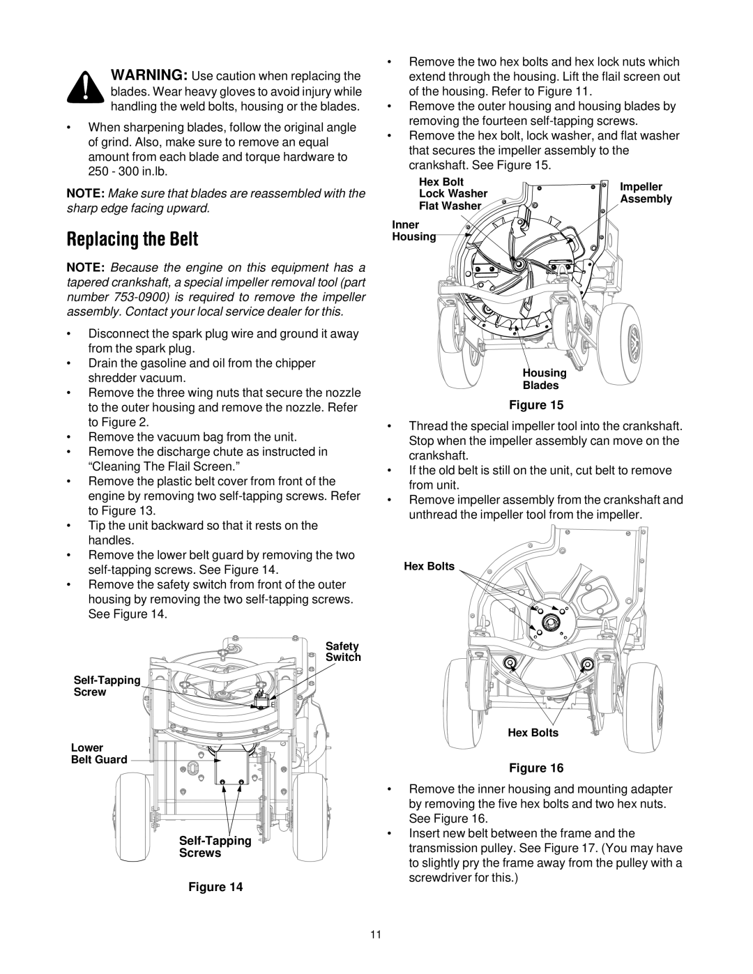
The Troy-Bilt CSV206 is a powerful and versatile chipper shredder that excels in both performance and ease of use, making it an ideal choice for homeowners looking to manage yard waste efficiently. With its robust construction and innovative technologies, this machine ensures effective shredding and chipping of garden debris, such as branches, leaves, and twigs.At the heart of the CSV206 is its reliable 206cc OHV engine, designed to deliver ample power for tackling heavy-duty tasks. The engine features a recoil start for quick and easy ignition, allowing users to jump straight into their yard clean-up without the hassle of complicated starting procedures. Coupled with a 78-pound weight, this chipper shredder strikes a good balance between portability and stability, allowing it to handle challenging terrains while maintaining its sturdiness.
The CSV206 showcases a unique 2-in-1 design, featuring a chipper and a shredder in one machine. Its 1.5-inch max chip capacity is ideal for tackling branches and larger-sized debris, making it perfect for maintaining a clean yard. The integrated shredding system efficiently reduces leaves and smaller materials into mulch, which can then be conveniently composted or used to enhance garden beds.
One noteworthy feature of the CSV206 is its large, versatile hopper. The top-loading design enables users to easily feed materials into the machine, which is complemented by a side discharge chute that directs shredded material precisely where it’s needed. This design reduces the effort and time needed for yard clean-up, making it a preferred choice among gardeners and landscapers.
User-friendly technology is evident in the CSV206's safety features, including a safety lid that ensures the chipper operates only when properly closed. Additionally, its durable steel construction ensures long-lasting performance, and the powder-coated finish helps resist rust and corrosion, extending the lifespan of the machine.
The Troy-Bilt CSV206 is also equipped with oversized wheels that enhance mobility, allowing users to navigate their yard smoothly, even across uneven terrain. With its blend of power, versatility, and user-friendly design, the Troy-Bilt CSV206 stands out as a great investment for anyone needing an efficient solution for yard waste management. Whether tackling seasonal clean-ups or maintaining regular yard maintenance, this chipper shredder promises to simplify the task and deliver impressive results.