TB4000 specifications
The Troy-Bilt TB4000 is a versatile and reliable workhorse designed for homeowners and landscapers alike. This compact tiller blends power, efficiency, and user-friendly features, making it an indispensable tool for garden enthusiasts looking to cultivate and maintain their soil.One of the standout features of the TB4000 is its robust engine. Equipped with a 4-cycle, 24.5cc engine, it delivers ample power to tackle tough soil conditions. This engine provides reliable performance while being easy to start thanks to its user-friendly recoil start mechanism. The four-stroke design eliminates the need for mixing fuel and oil, simplifying maintenance.
The TB4000 boasts a unique tilling capability that makes it suitable for a variety of gardening tasks. It features a 12-inch tilling width and adjustable tilling depth, allowing users to customize their tilling experience. Whether preparing a new garden bed or cultivating existing soil, the TB4000 can handle it with ease.
Durability is another important aspect of the TB4000's design. Its heavy-duty steel tines are built to withstand rigorous use and ensure longevity. The tiller is equipped with a front-mounted transport wheel, which makes it easy to maneuver from one location to another without straining the back or arms.
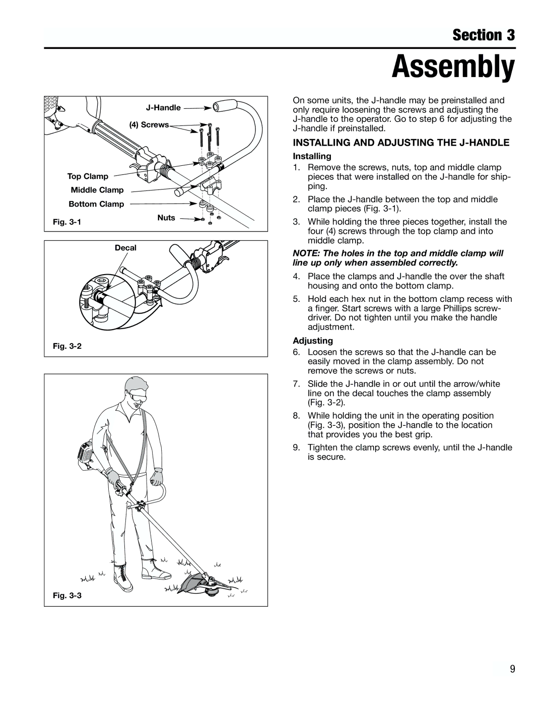
User comfort is also a major consideration in the design of the TB4000. The tiller features an ergonomic handle that can be adjusted for height, reducing strain during operation. Additionally, its lightweight design aids in overall control and ease of use.
For added convenience, the TB4000 offers a variety of tilling settings. It includes a forward-rotating tine mechanism, ideal for breaking up hard soil, while its adjustable speed allows for fine-tuning based on the task.
In terms of technology, the Troy-Bilt TB4000 comes equipped with enhancements that optimize performance. Its air filter system ensures that the engine runs smoothly by keeping dirt and debris at bay, which can be particularly useful in dusty conditions.
Overall, the Troy-Bilt TB4000 stands out in the realm of tillers, providing exceptional performance, durability, and user comfort. Whether you are new to gardening or a seasoned pro, this tiller is designed to meet the demands of various gardening tasks, making it an excellent investment for anyone dedicated to cultivating lush and healthy landscapes.

