PRECISION 8i | OPERATION MANUAL |
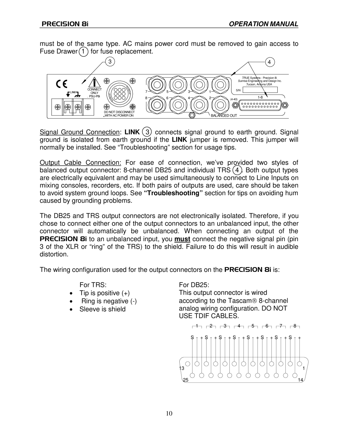
must be of the same type. AC mains power cord must be removed to gain access to Fuse Drawer 1 for fuse replacement.
|
| 3 |
|
|
|
| 4 |
|
|
|
|
|
|
| TRUE Systems - Precision 8i |
|
|
|
|
|
|
| Sunrise Engineering and Design Inc. |
|
|
|
|
|
|
| Tucson, Arizona USA |
LINK | CONNECT | 7 | 5 | 3 | 1 | S/N | |
ONLY |
|
| |||||
| 8 | 6 | 4 | 2 | |||
|
| ||||||
|
|
|
|
|
|
| |
|
| DO NOT DISCONNECT |
|
| BALANCED OUT |
| |
|
| WITH AC POWER ON |
|
|
| ||
Signal Ground Connection: LINK 3 connects signal ground to earth ground. Signal ground is isolated from earth ground if the LINK jumper is removed. This jumper will normally be installed. See “Troubleshooting”section for usage tips.
Output Cable Connection: For ease of connection, we’ve provided two styles of
balanced output connector:
The DB25 and TRS output connectors are not electronically isolated. Therefore, if you chose to connect either one of the output connectors to an unbalanced input, the other connector will automatically be unbalanced. When connecting an output of the PRECISION 8i to an unbalanced input, you must connect the negative signal pin (pin 3 of the XLR or “ring”of the TRS) to the shield. Failure to do this will result in audible distortion.
The wiring configuration used for the output connectors on the PRECISION 8i is:
For TRS:
∙ Tip is positive (+) ∙ Ring is negative
For DB25:
This output connector is wired according to the Tascam®
1 
 2
2 
 3
3 
 4
4 
 5
5 
 6
6 
 7
7
8
S - + S - + S - + S - + S - + S - + S - + S - +
13
1
25 | 14 | ||
|
|
|
|
10