Turbosound TA-500TDP, TA-500HDP Setting the angles between rows, Attaching the biscuit

Models: TA-500HM TA-500DP TA-500 TA-500H TA-500HDP TA-500T TA-500TDP

1 73
Download 73 pages 47.14 Kb
Page 32
Image 32
Setting the angles between rows

user manual

TA-500

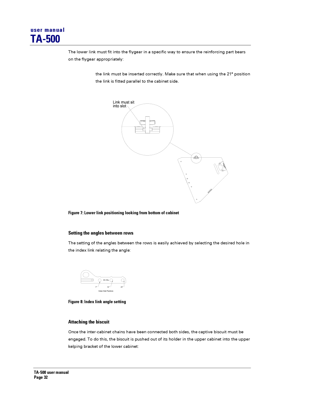
The lower link must fit into the flygear in a specific way to ensure the reinforcing part bears on the flygear appropriately:

the link must be inserted correctly. Make sure that when using the 21° position the link is fitted parallel to the cabinet side.

Figure 7: Lower link positioning looking from bottom of cabinet

Setting the angles between rows

The setting of the angles between the rows is easily achieved by selecting the desired hole in the index link relating the angle:

Figure 8: Index link angle setting

Attaching the biscuit

Once the inter-cabinet chains have been connected both sides, the captive biscuit must be engaged. To do this, the biscuit is pushed out of its holder in the upper cabinet into the upper kelping bracket of the lower cabinet:

TA-500 user manual

Page 32

Page 32
Image 32
Turbosound TA-500TDP, TA-500HDP Setting the angles between rows, Attaching the biscuit, Index link angle setting