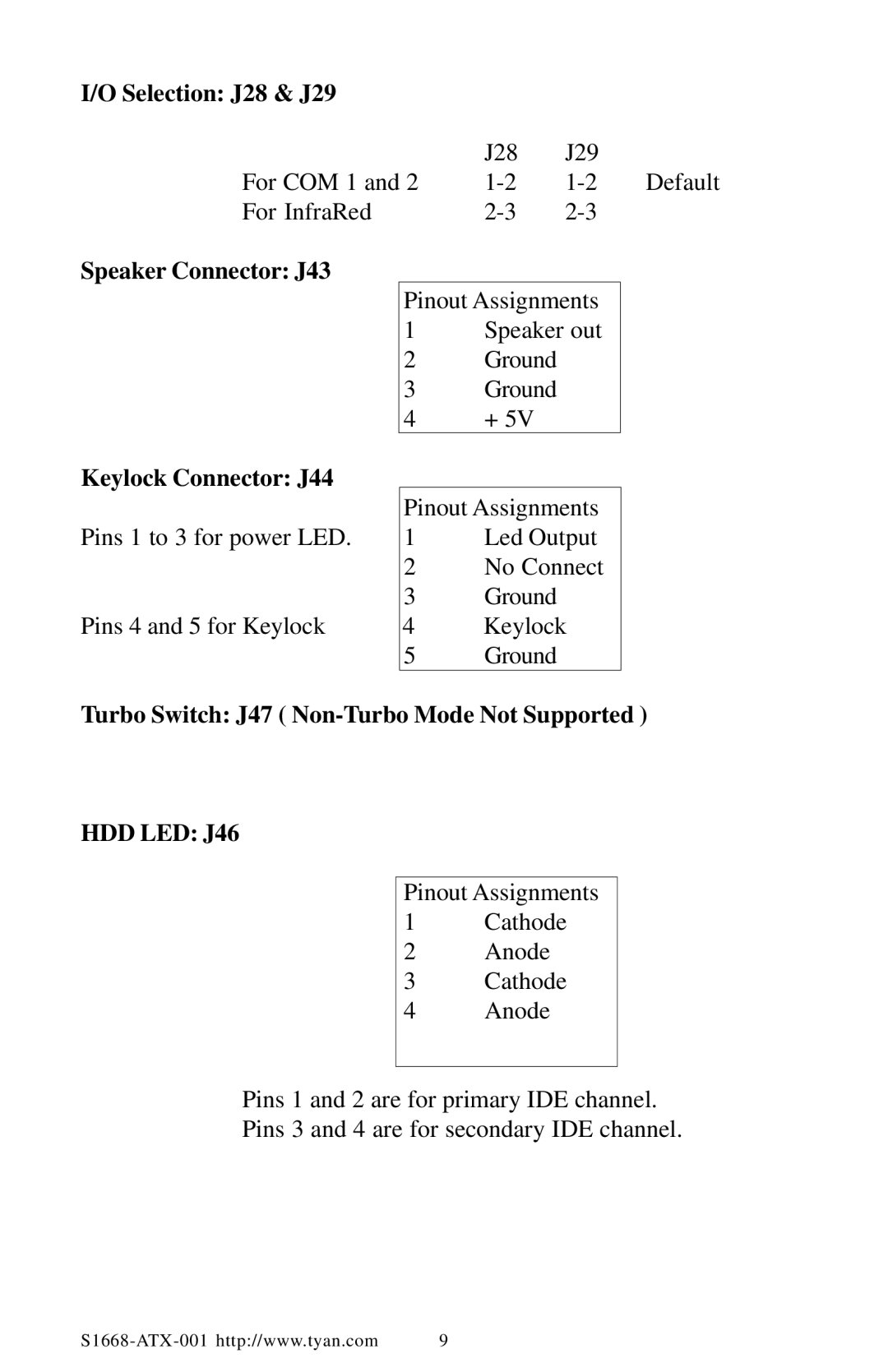
I/O Selection: J28 & J29 |
|
|
|
| J28 | J29 |
|
For COM 1 and 2 | Default | ||
For InfraRed |
|
Speaker Connector: J43
Keylock Connector: J44
Pins 1 to 3 for power LED.
Pins 4 and 5 for Keylock
Pinout Assignments
1Speaker out
2Ground
3Ground
4+ 5V
Pinout Assignments
1Led Output
2No Connect
3Ground
4Keylock
5Ground
Turbo Switch: J47 ( Non-Turbo Mode Not Supported )
HDD LED: J46
Pinout Assignments
1 | Cathode |
2 | Anode |
3 | Cathode |
4 | Anode |
Pins 1 and 2 are for primary IDE channel.
Pins 3 and 4 are for secondary IDE channel.
9 |
