
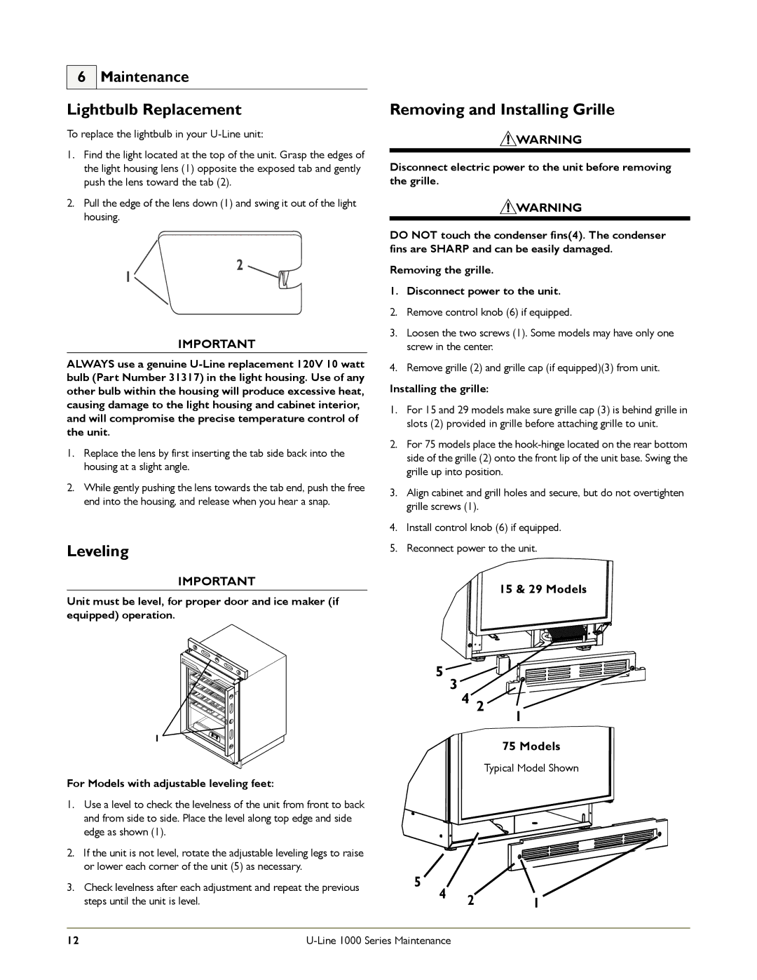
1175WC specifications
U-Line has long been a leader in the realm of premium refrigeration, and their U-Line 1115WC and 1175WC models have set a new standard for versatility and performance in compact wine coolers. Designed for wine enthusiasts, these models encapsulate a harmonious blend of style, temperature control, and innovative features that bring elegance to any space.The U-Line 1115WC, with its 15-inch width, is perfect for smaller areas, making it an ideal choice for apartments, kitchens, or home bars. In contrast, the U-Line 1175WC, slightly wider at 17.5 inches, provides additional storage capacity without compromising on aesthetics. Both models boast a sleek, stainless steel frame and a glass door that not only showcases the wine collection but also adds a modern touch to any decor.
A standout feature of these wine coolers is their advanced cooling technology. U-Line employs a dual-zone cooling system, allowing you to set different temperatures for red and white wines, ensuring ideal preservation conditions. The temperature can be adjusted within the range of 34°F to 65°F, catering to various preferences for wine serving temperatures.
For those who appreciate a quiet environment, both models are engineered with a remarkably low decibel level, ensuring minimal operational noise. This feature makes them perfect for integration into social spaces, where conversation and ambience are important.
Another notable characteristic is the adjustable shelving system. Both wine coolers come with removable, natural wood shelves that can accommodate bottles of varying sizes. The shelves are designed to prevent bottles from rolling while providing easy access. With the capacity to hold up to 24 bottles in the 1115WC and up to 30 bottles in the 1175WC, storage is both efficient and organized.
The U-Line 1115WC and 1175WC also come equipped with a digital control panel, allowing users to easily monitor and set the internal temperature. The soft LED lighting serves to enhance visibility while showcasing your wine collection without affecting the wine’s quality.
In conclusion, the U-Line 1115WC and 1175WC wine coolers combine functionality, stylish design, and advanced technology to deliver an exceptional wine storage experience. Whether you're a novice collector or a seasoned sommelier, these models offer the perfect solution for preserving and displaying your cherished wines.