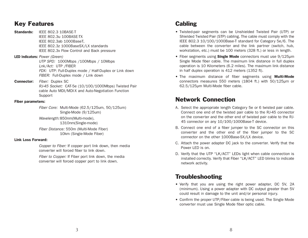
GEP-5400TF-C, GEP-5300TF-C specifications
UNICOM Electric has gained recognition in the energy sector for its innovative solutions in power management. Among its premier offerings are the GEP-5400TF-C and GEP-5300TF-C models. Both of these advanced devices are designed to address the evolving needs of industrial and commercial applications, ensuring higher efficiency and reliability.The GEP-5400TF-C stands out with its unique features. It is engineered with a robust, high-performance processing unit that enables fast and precise control. This unit is complemented by a state-of-the-art user interface, allowing operators to easily navigate the device's functionalities. With a focus on energy optimization, the GEP-5400TF-C incorporates advanced algorithms that analyze energy consumption in real time. This ensures operational costs are minimized while maximizing productivity.
On the other hand, the GEP-5300TF-C offers a versatile solution for energy management. It is equipped with multiple communication protocols, which facilitate seamless integration with existing infrastructure. This model supports a wide array of sensors and can be customized to meet specific operational requirements. The design prioritizes modularity, making it easy to upgrade and maintain, ultimately extending the equipment's lifecycle.
Both models incorporate cutting-edge technologies, such as remote monitoring and control capabilities. This feature allows users to oversee operations from anywhere in the world, fostering better decision-making through data analytics. The devices are also built with durable components that are resistant to harsh environmental conditions, assuring reliability in demanding settings.
Energy efficiency is further enhanced by their ability to support renewable energy sources. The GEP-5400TF-C and GEP-5300TF-C can be integrated with solar panels and wind turbines, contributing to a more sustainable energy ecosystem. Their user-friendly configuration options ensure that users can adapt the systems to fit their specific energy needs without extensive downtime.
In summary, UNICOM Electric's GEP-5400TF-C and GEP-5300TF-C models showcase a blend of advanced technology and practical design. With their robust processing capabilities, adaptability to renewable energy, and seamless communication protocols, these devices are pivotal for businesses looking to enhance their energy management strategies. They represent a significant step forward in achieving operational efficiency and sustainability in an increasingly energy-conscious world.
