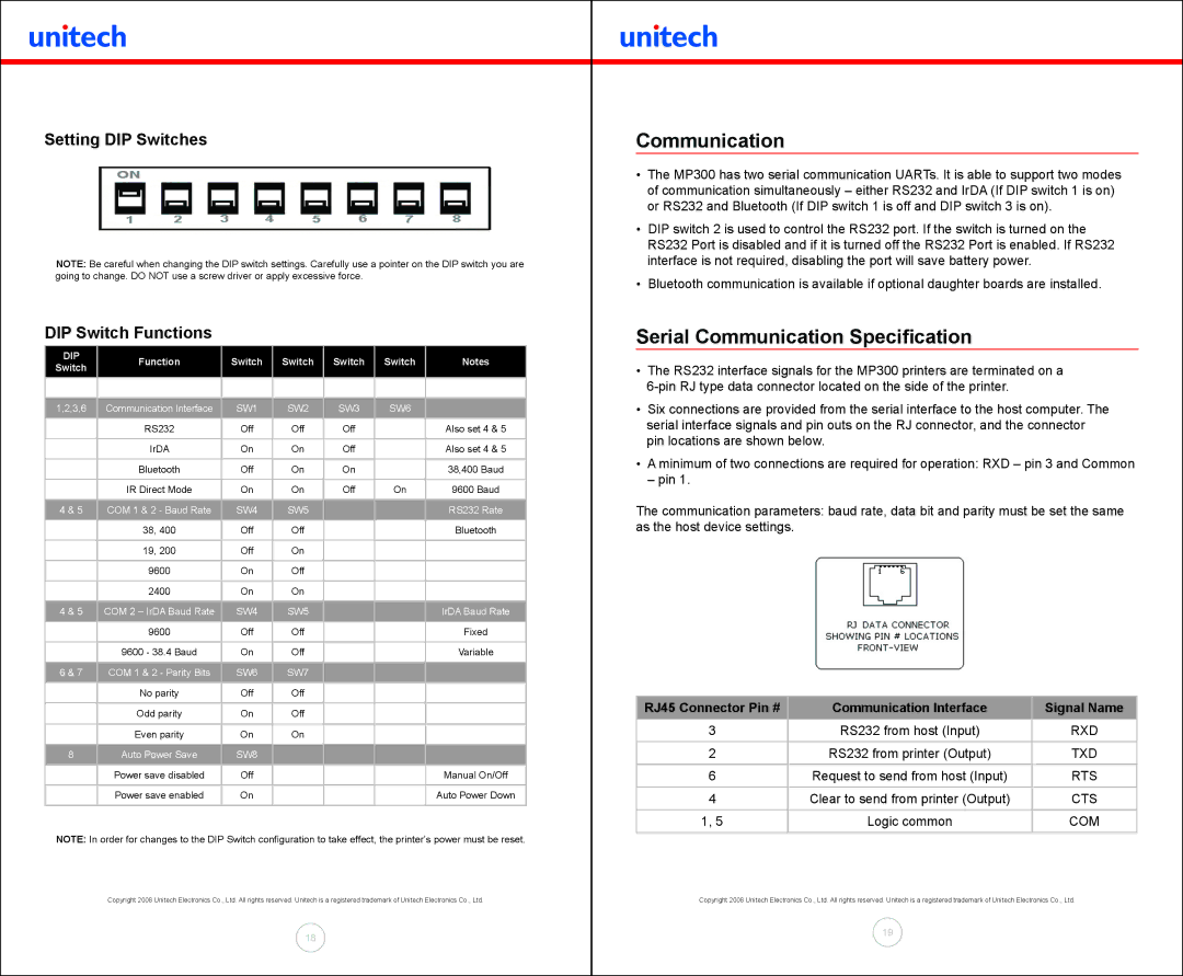
Setting DIP Switches
!
NOTE: Be careful when changing the DIP switch settings. Carefully use a pointer on the DIP switch you are going to change. DO NOT use a screw driver or apply excessive force.
DIP Switch Functions
DIP | Function | Switch | Switch | Switch | Switch | Notes | |
Switch | |||||||
|
|
|
|
|
| ||
|
|
|
|
|
|
| |
|
|
|
|
|
|
| |
1,2,3,6 | Communication Interface | SW1 | SW2 | SW3 | SW6 |
| |
|
|
|
|
|
|
| |
| RS232 | Off | Off | Off |
| Also set 4 & 5 | |
|
|
|
|
|
|
| |
| IrDA | On | On | Off |
| Also set 4 & 5 | |
|
|
|
|
|
|
| |
| Bluetooth | Off | On | On |
| 38,400 Baud | |
|
|
|
|
|
|
| |
| IR Direct Mode | On | On | Off | On | 9600 Baud | |
|
|
|
|
|
|
| |
4 & 5 | COM 1 & 2 - Baud Rate | SW4 | SW5 |
|
| RS232 Rate | |
|
|
|
|
|
|
| |
| 38, 400 | Off | Off |
|
| Bluetooth | |
|
|
|
|
|
|
| |
| 19, 200 | Off | On |
|
|
| |
|
|
|
|
|
|
| |
| 9600 | On | Off |
|
|
| |
|
|
|
|
|
|
| |
| 2400 | On | On |
|
|
| |
|
|
|
|
|
|
| |
4 & 5 | COM 2 – IrDA Baud Rate | SW4 | SW5 |
|
| IrDA Baud Rate | |
|
|
|
|
|
|
| |
| 9600 | Off | Off |
|
| Fixed | |
|
|
|
|
|
|
| |
| 9600 - 38.4 Baud | On | Off |
|
| Variable | |
|
|
|
|
|
|
| |
6 & 7 | COM 1 & 2 - Parity Bits | SW6 | SW7 |
|
|
| |
|
|
|
|
|
|
| |
| No parity | Off | Off |
|
|
| |
|
|
|
|
|
|
| |
| Odd parity | On | Off |
|
|
| |
|
|
|
|
|
|
| |
| Even parity | On | On |
|
|
| |
|
|
|
|
|
|
| |
8 | Auto Power Save | SW8 |
|
|
|
| |
|
|
|
|
|
|
| |
| Power save disabled | Off |
|
|
| Manual On/Off | |
|
|
|
|
|
|
| |
| Power save enabled | On |
|
|
| Auto Power Down | |
|
|
|
|
|
|
|
NOTE: In order for changes to the DIP Switch configuration to take effect, the printer’s power must be reset.
Copyright 2008 Unitech Electronics Co., Ltd. All rights reserved. Unitech is a registered trademark of Unitech Electronics Co., Ltd.
18
Communication
•The MP300 has two serial communication UARTs. It is able to support two modes of communication simultaneously – either RS232 and IrDA (If DIP switch 1 is on) or RS232 and Bluetooth (If DIP switch 1 is off and DIP switch 3 is on).
•DIP switch 2 is used to control the RS232 port. If the switch is turned on the RS232 Port is disabled and if it is turned off the RS232 Port is enabled. If RS232 interface is not required, disabling the port will save battery power.
•Bluetooth communication is available if optional daughter boards are installed.
Serial Communication Specification
•The RS232 interface signals for the MP300 printers are terminated on a
•Six connections are provided from the serial interface to the host computer. The serial interface signals and pin outs on the RJ connector, and the connector pin locations are shown below.
•A minimum of two connections are required for operation: RXD – pin 3 and Common
– pin 1.
The communication parameters: baud rate, data bit and parity must be set the same as the host device settings.
| ! |
|
|
|
|
RJ45 Connector Pin # | Communication Interface | Signal Name |
3 | RS232 from host (Input) | RXD |
2 | RS232 from printer (Output) | TXD |
|
|
|
6 | Request to send from host (Input) | RTS |
4 | Clear to send from printer (Output) | CTS |
|
|
|
1, 5 | Logic common | COM |
Copyright 2008 Unitech Electronics Co., Ltd. All rights reserved. Unitech is a registered trademark of Unitech Electronics Co., Ltd.
19