USSC
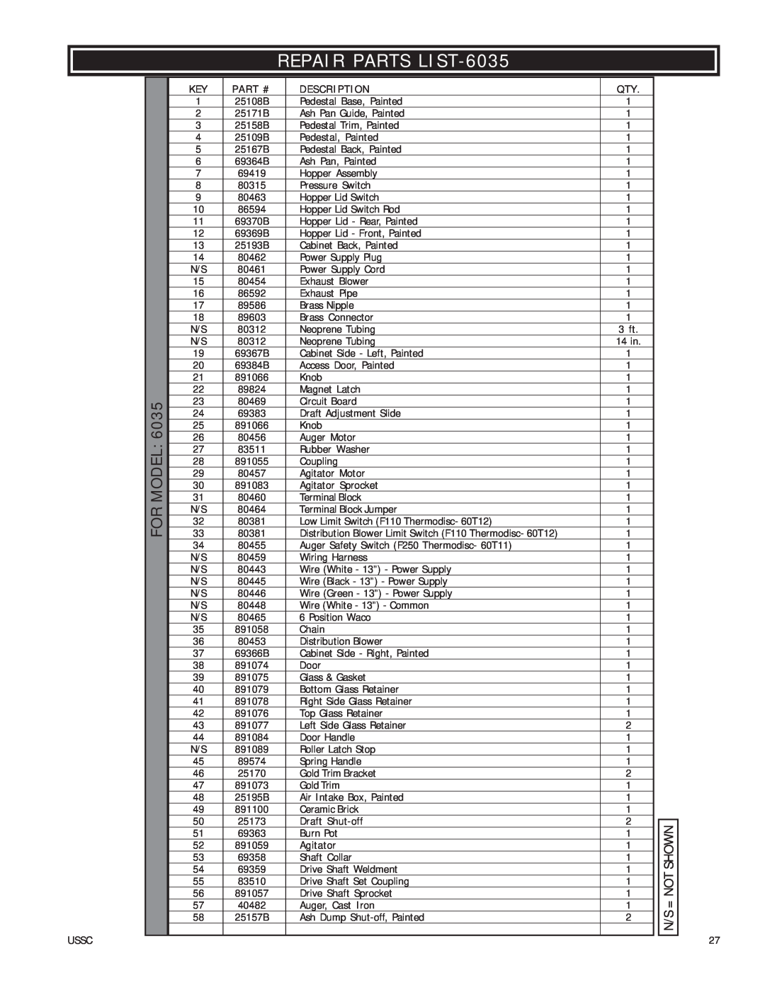
REPAIR PARTS LIST-6035
| KEY | PART # | DESCRIPTION | QTY. |
|
|
| 1 | 25108B | Pedestal Base, Painted | 1 |
|
|
| 2 | 25171B | Ash Pan Guide, Painted | 1 |
|
|
| 3 | 25158B | Pedestal Trim, Painted | 1 |
|
|
| 4 | 25109B | Pedestal, Painted | 1 |
|
|
| 5 | 25167B | Pedestal Back, Painted | 1 |
|
|
| 6 | 69364B | Ash Pan, Painted | 1 |
|
|
| 7 | 69419 | Hopper Assembly | 1 |
|
|
| 8 | 80315 | Pressure Switch | 1 |
|
|
| 9 | 80463 | Hopper Lid Switch | 1 |
|
|
| 10 | 86594 | Hopper Lid Switch Rod | 1 |
|
|
| 11 | 69370B | Hopper Lid - Rear, Painted | 1 |
|
|
| 12 | 69369B | Hopper Lid - Front, Painted | 1 |
|
|
| 13 | 25193B | Cabinet Back, Painted | 1 |
|
|
| 14 | 80462 | Power Supply Plug | 1 |
|
|
| N/S | 80461 | Power Supply Cord | 1 |
|
|
| 15 | 80454 | Exhaust Blower | 1 |
|
|
| 16 | 86592 | Exhaust Pipe | 1 |
|
|
| 17 | 89586 | Brass Nipple | 1 |
|
|
| 18 | 89603 | Brass Connector | 1 |
|
|
| N/S | 80312 | Neoprene Tubing | 3 ft. |
|
|
| N/S | 80312 | Neoprene Tubing | 14 in. |
|
|
| 19 | 69367B | Cabinet Side - Left, Painted | 1 |
|
|
| 20 | 69384B | Access Door, Painted | 1 |
|
|
| 21 | 891066 | Knob | 1 |
|
|
| 22 | 89824 | Magnet Latch | 1 |
|
|
6035 | 23 | 80469 | Circuit Board | 1 |
|
|
| 24 | 69383 | Draft Adjustment Slide | 1 |
|
|
| 25 | 891066 | Knob | 1 |
|
|
MODEL: | 26 | 80456 | Auger Motor | 1 |
|
|
27 | 83511 | Rubber Washer | 1 |
|
| |
31 | 80460 | Terminal Block | 1 |
|
| |
| 28 | 891055 | Coupling | 1 |
|
|
| 29 | 80457 | Agitator Motor | 1 |
|
|
| 30 | 891083 | Agitator Sprocket | 1 |
|
|
|
|
|
|
|
|
|
FOR | N/S | 80464 | Terminal Block Jumper | 1 |
|
|
32 | 80381 | Low Limit Switch (F110 Thermodisc- 60T12) | 1 |
|
| |
33 | 80381 | Distribution Blower Limit Switch (F110 Thermodisc- 60T12) | 1 |
|
| |
| 34 | 80455 | Auger Safety Switch (F250 Thermodisc- 60T11) | 1 |
|
|
| N/S | 80459 | Wiring Harness | 1 |
|
|
| N/S | 80443 | Wire (White - 13”) - Power Supply | 1 |
|
|
| N/S | 80445 | Wire (Black - 13”) - Power Supply | 1 |
|
|
| N/S | 80446 | Wire (Green - 13”) - Power Supply | 1 |
|
|
| N/S | 80448 | Wire (White - 13”) - Common | 1 |
|
|
| N/S | 80465 | 6 Position Waco | 1 |
|
|
| 35 | 891058 | Chain | 1 |
|
|
| 36 | 80453 | Distribution Blower | 1 |
|
|
| 37 | 69366B | Cabinet Side - Right, Painted | 1 |
|
|
| 38 | 891074 | Door | 1 |
|
|
| 39 | 891075 | Glass & Gasket | 1 |
|
|
| 40 | 891079 | Bottom Glass Retainer | 1 |
|
|
| 41 | 891078 | Right Side Glass Retainer | 1 |
|
|
| 42 | 891076 | Top Glass Retainer | 1 |
|
|
| 43 | 891077 | Left Side Glass Retainer | 2 |
|
|
| 44 | 891084 | Door Handle | 1 |
|
|
| N/S | 891089 | Roller Latch Stop | 1 |
|
|
| 45 | 89574 | Spring Handle | 1 |
|
|
| 46 | 25170 | Gold Trim Bracket | 2 |
|
|
| 47 | 891073 | Gold Trim | 1 |
|
|
| 48 | 25195B | Air Intake Box, Painted | 1 |
|
|
| 49 | 891100 | Ceramic Brick | 1 |
|
|
| 50 | 25173 | Draft | 2 |
|
|
|
| SHOWN | ||||
| 51 | 69363 | Burn Pot | 1 |
|
|
| 52 | 891059 | Agitator | 1 |
|
|
| 53 | 69358 | Shaft Collar | 1 |
|
|
| 54 | 69359 | Drive Shaft Weldment | 1 |
| NOT |
| 55 | 83510 | Drive Shaft Set Coupling | 1 |
| |
| 56 | 891057 | Drive Shaft Sprocket | 1 |
| |
|
|
|
|
| = | |
| 57 | 40482 | Auger, Cast Iron | 1 | ||
|
|
|
|
| ||
|
|
|
|
|
| N/S |
| 58 | 25157B | Ash Dump | 2 |
| |
|
|
|
|
|
| |
27