5
PowerBlasterTM
Parts Guide
Quantity Description
1PowerBlaster™ Receiver with integrated antenna
1Mounting Plate for wall mounting PowerBlaster™
4Screws for wall mounting the mounting plate
1
6Flashers with 10 foot
The Mounting Plate
6
PowerBlasterTM
PARTS GUIDE
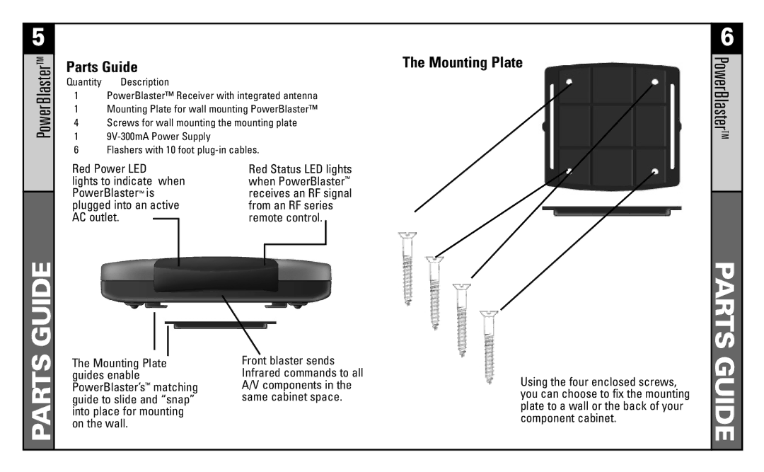
Red Power LED
lights to indicate when PowerBlaster™ is plugged into an active AC outlet.
The Mounting Plate guides enable PowerBlaster’s™ matching guide to slide and “snap” into place for mounting on the wall.
Red Status LED lights when PowerBlaster™ receives an RF signal from an RF series remote control.
Front blaster sends Infrared commands to all A/V components in the same cabinet space.
Using the four enclosed screws, you can choose to fix the mounting plate to a wall or the back of your component cabinet.
PARTS GUIDE