FIGURE 2 |
|
|
| 7 |
|
| 27 | 8 |
13 | 24 |
|
| 3/8 X | 17 |
| 16 3/8 X 2” |
|
STEP 2:
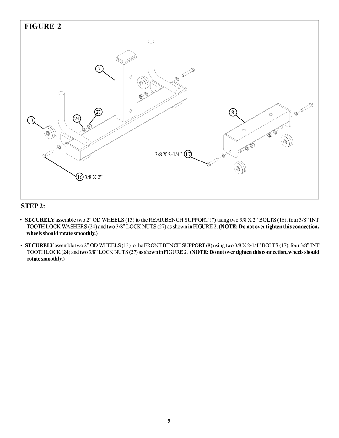
•SECURELY assemble two 2” OD WHEELS (13) to the REAR BENCH SUPPORT (7) using two 3/8 X 2” BOLTS (16), four 3/8” INT TOOTH LOCK WASHERS (24) and two 3/8” LOCK NUTS (27) as shown in FIGURE 2. (NOTE: Do not over tighten this connection, wheels should rotate smoothly.)
•SECURELY assemble two 2” OD WHEELS (13) to the FRONT BENCH SUPPORT (8) using two 3/8 X
5
