INSTALLATION
NOTE: The telephone system referred to in this manual is the customer premise equipment such as an electronic key system, a PBX or a dedicated single line telephone sets. The
Precautionary Designations
CAUTION
RISK OF ELECTRIC SHOCK
DO NOT OPEN
CAUTION: To reduce the risk of electric shock,
Do not remove cover.
No user serviceable parts inside.
Refer servicing to qualified service personnel.
This symbol indicates that dangerous voltage constituting a risk of electric shock is present within this unit.
This symbol indicates that there are important operating and maintenance instructions in the literature accompanying this unit.
FCC Information
This equipment has been tested and found to comply with the limits for a Class A digital device, pursuant to Part 15 of the FCC Rules. These limits are designed to provide reasonable protection against harmful interference when the equipment is operated in a commercial environment. This equipment generates, uses and can radiate radio frequency energy and if not installed and used in accordance with the instruction manual, may cause harmful interference to radio communications. Operation of this equipment in a residential area may cause harmful interference in which case the user will be required to correct the interference at his own expense.
Mounting
The
Table: Provided with the
Wall: Using the template and instructions provided, secure the
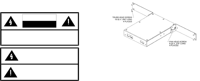
Rack: Following the assembly drawing, attach the two mounting ears to the
Power Connections
The preferred method of powering a
If the rear panel barrel connector is used for power, the preferred power supply is a Valcom
Make all required signal connections before applying power to the unit. If powering via 802.3af, make sure all signal connections via the back panel are made then connect the
If power is supplied via the barrel connector, make sure all signal connections are secure. Attach the unit to the network via the front panel
2 | 947998 |