Manuals
/
Vector
/
Lawn and Garden
/
Portable Generator
Vector
SMATE200A
manual
Configuration Examples, One baseband generator and one RF path, SMATE-B10
Models:
SMATE200A
1
10
14
14
Download
14 pages
5.72 Kb
7
8
9
10
11
12
13
14
Page 10
Image 10
Page 9
Page 11
Page 10
Image 10
Page 9
Page 11
Contents
April
Vector Signal Generator ¸SMATE 200A
Configuration Guide
Version
The variety of signal generation for production
Option overview
Choose output configuration
Step c Configure RF path
Step d Configure baseband path
Single-pathinstrument
Choose noise
Step d Configure RF path B
Step c Configure RF path A
Two-pathinstrument
Step e Configure baseband path A
Step f Configure baseband path B
OPTIONAL
SMATE-B10 SMATE-B13SMATEB10x
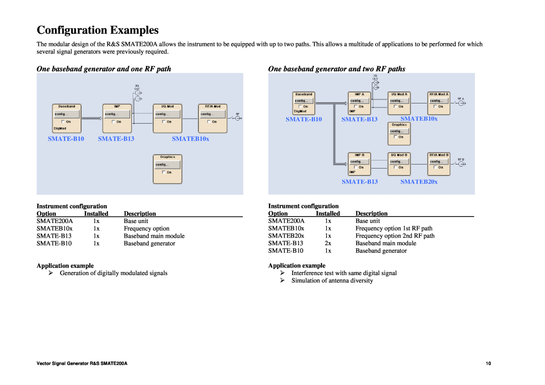
Configuration Examples
One baseband generator and one RF path
SMATE-B10
SMATE-B10 SMATE-B13 SMATEB10x
One baseband generator and two RF paths
Two baseband generators and two RF paths
SMATE-B10 SMATE-B13SMATEB20x
Vector Signal Generator1
Ordering information
Options
Recommended extras
Top
Page
Image
Contents