VEC128SL_ManualEN_092605 9/26/05 9:20 AM Page 7
1.INTRODUCTION
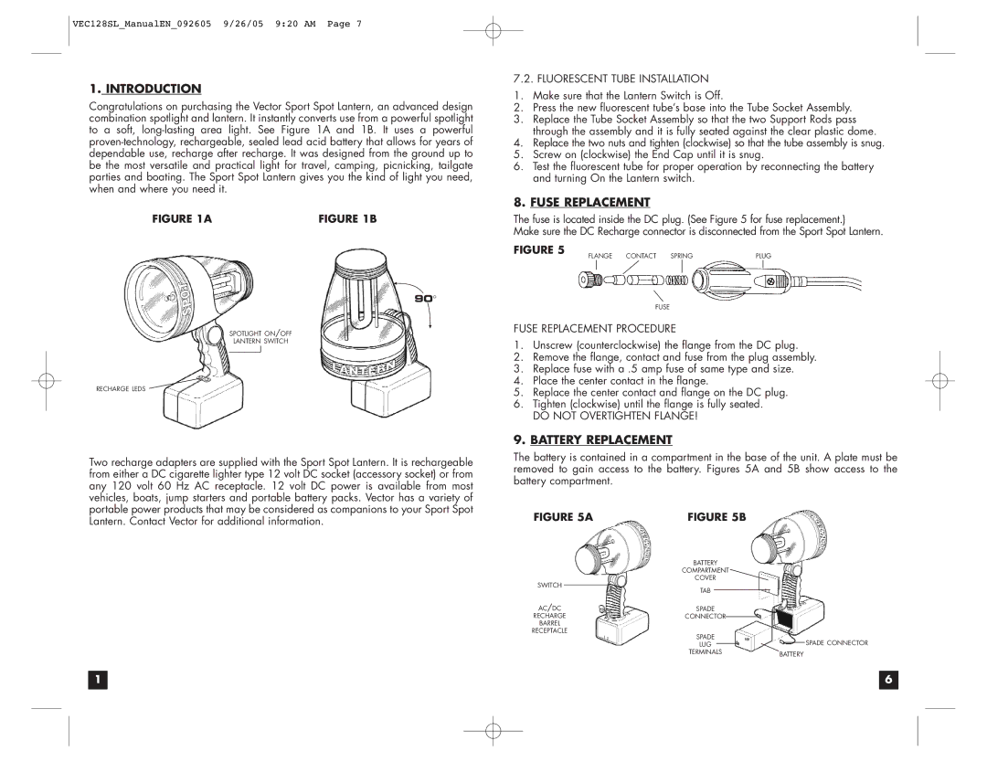
Congratulations on purchasing the Vector Sport Spot Lantern, an advanced design combination spotlight and lantern. It instantly converts use from a powerful spotlight to a soft,
FIGURE 1A | FIGURE 1B |
![]()
![]() °
°
SPOTLIGHT ON/OFF
LANTERN SWITCH
RECHARGE LEDS
Two recharge adapters are supplied with the Sport Spot Lantern. It is rechargeable from either a DC cigarette lighter type 12 volt DC socket (accessory socket) or from any 120 volt 60 Hz AC receptacle. 12 volt DC power is available from most vehicles, boats, jump starters and portable battery packs. Vector has a variety of portable power products that may be considered as companions to your Sport Spot Lantern. Contact Vector for additional information.
7.2. FLUORESCENT TUBE INSTALLATION
1.Make sure that the Lantern Switch is Off.
2.Press the new fluorescent tube’s base into the Tube Socket Assembly.
3.Replace the Tube Socket Assembly so that the two Support Rods pass through the assembly and it is fully seated against the clear plastic dome.
4.Replace the two nuts and tighten (clockwise) so that the tube assembly is snug.
5.Screw on (clockwise) the End Cap until it is snug.
6.Test the fluorescent tube for proper operation by reconnecting the battery and turning On the Lantern switch.
8.FUSE REPLACEMENT
The fuse is located inside the DC plug. (See Figure 5 for fuse replacement.)
Make sure the DC Recharge connector is disconnected from the Sport Spot Lantern.
FIGURE 5 | FLANGE CONTACT SPRING | PLUG |
|
FUSE
FUSE REPLACEMENT PROCEDURE
1.Unscrew (counterclockwise) the flange from the DC plug.
2.Remove the flange, contact and fuse from the plug assembly.
3.Replace fuse with a .5 amp fuse of same type and size.
4.Place the center contact in the flange.
5.Replace the center contact and flange on the DC plug.
6.Tighten (clockwise) until the flange is fully seated.
DO NOT OVERTIGHTEN FLANGE!
9.BATTERY REPLACEMENT
The battery is contained in a compartment in the base of the unit. A plate must be removed to gain access to the battery. Figures 5A and 5B show access to the battery compartment.
FIGURE 5A | FIGURE 5B |
|
|
| ||||
|
| BATTERY |
|
|
| |||
|
| COMPARTMENT |
|
|
| |||
SWITCH |
| COVER |
|
|
| |||
| TAB |
|
|
|
|
|
| |
|
|
|
|
|
|
| ||
AC/DC |
|
|
|
|
|
| ||
SPADE |
|
|
| |||||
RECHARGE | CONNECTOR |
|
|
|
|
| ||
|
|
|
| |||||
BARREL |
|
|
|
|
|
|
| |
RECEPTACLE | SPADE |
|
|
| ||||
|
|
|
| SPADE CONNECTOR | ||||
|
| LUG |
|
| ||||
|
|
|
| |||||
|
| TERMINALS | BATTERY | |||||
|
|
|
|
|
| |||
1 |
| 6 |
|
|
|
