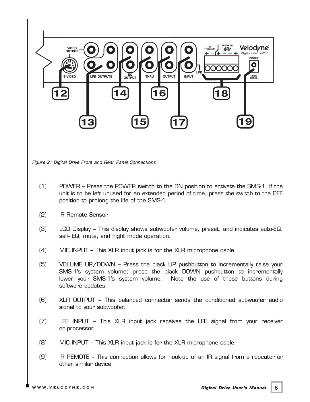
Figure 2: Digital Drive Front and Rear Panel Connections
(1)POWER – Press the POWER switch to the ON position to activate the
(2)IR Remote Sensor.
(3)LCD Display – This display shows subwoofer volume, preset, and indicates
(4)MIC INPUT – This XLR input jack is for the XLR microphone cable.
(5)VOLUME UP/DOWN – Press the black UP pushbutton to incrementally raise your
(6)XLR OUTPUT – This balanced connector sends the conditioned subwoofer audio signal to your subwoofer.
(7) | LFE INPUT – This XLR input jack receives the LFE signal from your receiver |
| or processor. |
(8)MIC INPUT – This XLR input jack is for the XLR microphone cable.
(9)IR REMOTE – This connection allows for
.w w w . v e l o d y n e . c o m | Digital Drive User’s Manual | 6 |