UNIT REFERENCE GUIDE
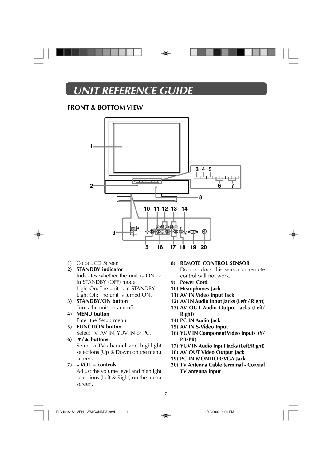
FRONT & BOTTOM VIEW
1)Color LCD Screen
2)STANDBY indicator
Indicates whether the unit is ON or in STANDBY (OFF) mode.
Light On: The unit is in STANDBY.
Light Off: The unit is turned ON.
3)STANDBY/ON button Turns the unit on and off.
4)MENU button
Enter the Setup menu.
5)FUNCTION button
Select TV, AV IN, YUV IN or PC.
6)![]() /
/ ![]() buttons
buttons
Select a TV channel and highlight selections (Up & Down) on the menu screen.
7)– VOL + controls
Adjust the volume level and highlight selections (Left & Right) on the menu screen.
8)REMOTE CONTROL SENSOR
Do not block this sensor or remote control will not work.
9)Power Cord
10)Headphones Jack
11)AV IN Video Input Jack
12)AV IN Audio Input Jacks (Left / Right)
13)AV OUT Audio Output Jacks (Left/ Right)
14)PC IN Audio Jack
15)AV IN
16)YUV IN ComponentVideo Inputs (Y/ PB/PR)
17)YUV IN Audio Input Jacks (Left/Right)
18)AV OUT Video Output Jack
19)PC IN MONITOR/VGA Jack
20)TV Antenna Cable terminal - Coaxial TV antenna input
7
PLV16151S1 VEN - WM CANADA.pmd | 7 | 1/10/2007, 5:06 PM |
