UNIT REFERENCE GUIDE | |
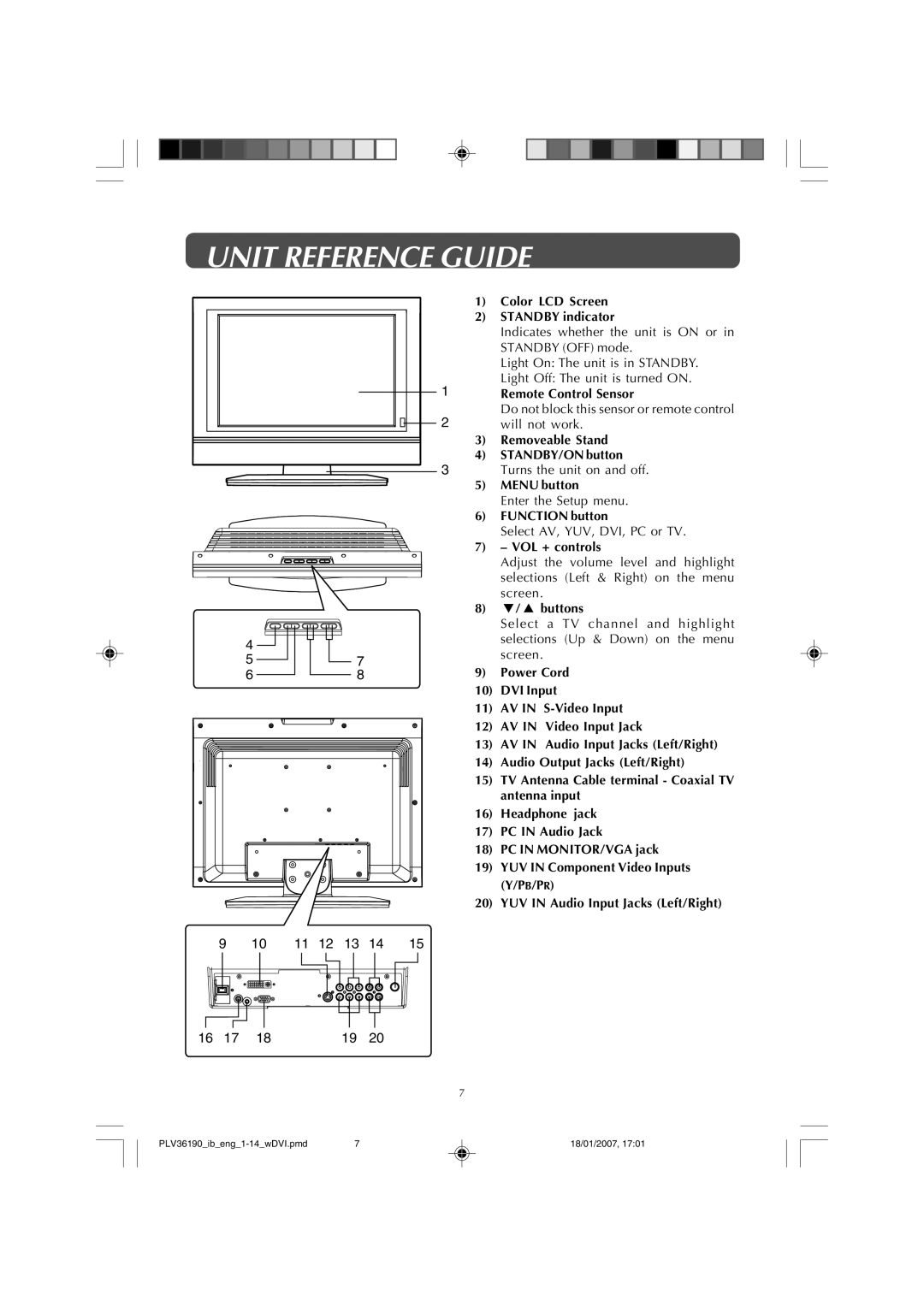
1) | Color LCD Screen |
2) | STANDBY indicator |
| Indicates whether the unit is ON or in |
| STANDBY (OFF) mode. |
| Light On: The unit is in STANDBY. |
1 | Light Off: The unit is turned ON. |
Remote Control Sensor | |
2 | Do not block this sensor or remote control |
will not work. | |
3) | Removeable Stand |
4) | STANDBY/ON button |
3 | Turns the unit on and off. |
4
57
68
5)MENU button
Enter the Setup menu.
6)FUNCTION button
Select AV, YUV, DVI, PC or TV.
7)– VOL + controls
Adjust the volume level and highlight selections (Left & Right) on the menu screen.
8)![]() /
/ ![]() buttons
buttons
Select a TV channel and highlight selections (Up & Down) on the menu screen.
9)Power Cord
10)DVI Input
11)AV IN
12)AV IN Video Input Jack
13)AV IN Audio Input Jacks (Left/Right)
14)Audio Output Jacks (Left/Right)
15)TV Antenna Cable terminal - Coaxial TV antenna input
16)Headphone jack
17)PC IN Audio Jack
18)PC IN MONITOR/VGA jack
19)YUV IN Component Video Inputs (Y/PB/PR)
20)YUV IN Audio Input Jacks (Left/Right)
9 | 10 |
|
| 11 | 12 | 13 | 14 | 15 | |||
|
|
|
|
|
|
|
|
|
|
|
|
|
|
|
|
|
|
|
|
|
|
|
|
16 | 17 | 18 | 19 | 20 |
7
7 | 18/01/2007, 17:01 |
