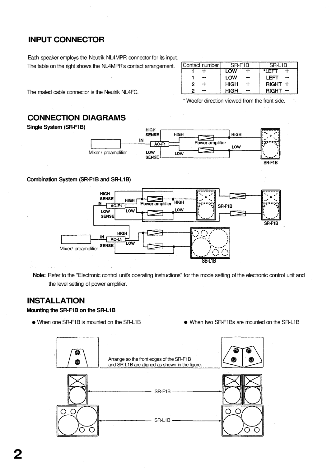
SR-F1B specifications
Verizon SR-F1B is an advanced telecommunications solution designed to enhance connectivity and enable improved communication services. As part of Verizon’s commitment to delivering reliable and robust network infrastructure, the SR-F1B combines a myriad of features and technologies that cater to both individual users and enterprises.One of the standout features of the Verizon SR-F1B is its support for high-speed data transmission. Capable of managing vast amounts of data traffic, it is ideally suited for environments that require steady and dependable connectivity, such as corporate offices, educational institutions, and industrial facilities. The device leverages Verizon's extensive 4G LTE and emerging 5G networks, ensuring users benefit from lightning-fast upload and download speeds.
The SR-F1B is designed with versatility in mind. It includes multiple connectivity options, including Ethernet ports, Wi-Fi, and support for VoIP, allowing seamless integration into a variety of network configurations. This adaptability makes it an excellent choice for businesses looking to upgrade their communication systems without significant infrastructure changes.
In terms of security, the Verizon SR-F1B incorporates advanced encryption protocols and security measures, ensuring that sensitive information transmitted over the network is safeguarded from potential threats. Additionally, its built-in firewall capabilities offer another layer of protection against unauthorized access and cyber attacks.
Another key characteristic of the SR-F1B is its scalability. As businesses grow, their communication needs evolve. The SR-F1B can be easily upgraded or expanded to accommodate increased traffic and additional services, ensuring long-term utility and value.
Moreover, the device supports enhanced quality of service (QoS) features that help prioritize critical communications and applications. This ensures that video conferencing, VoIP calls, and other bandwidth-sensitive applications perform optimally, even during peak usage times.
Lastly, the Verizon SR-F1B boasts a user-friendly interface that simplifies management and monitoring. Network administrators can easily access performance metrics, change configurations, and troubleshoot issues, all from a centralized dashboard, making it an efficient tool for maintaining operational excellence.
In summary, Verizon SR-F1B is a powerful communication solution that combines speed, versatility, security, scalability, and ease of use, making it an ideal choice for a variety of organizational needs. With its advanced technological features, it stands as a testament to Verizon's dedication to fostering an interconnected and efficient world.

