•The outside air duct’s inlet must be lower than the primary air inlet of the firebox, to prevent air infiltration.
•The air inlet must be covered by a wire mesh screen with openings not larger than 1/4” x 1/4” (6 x 6mm) to prevent rodents entering from the outside.
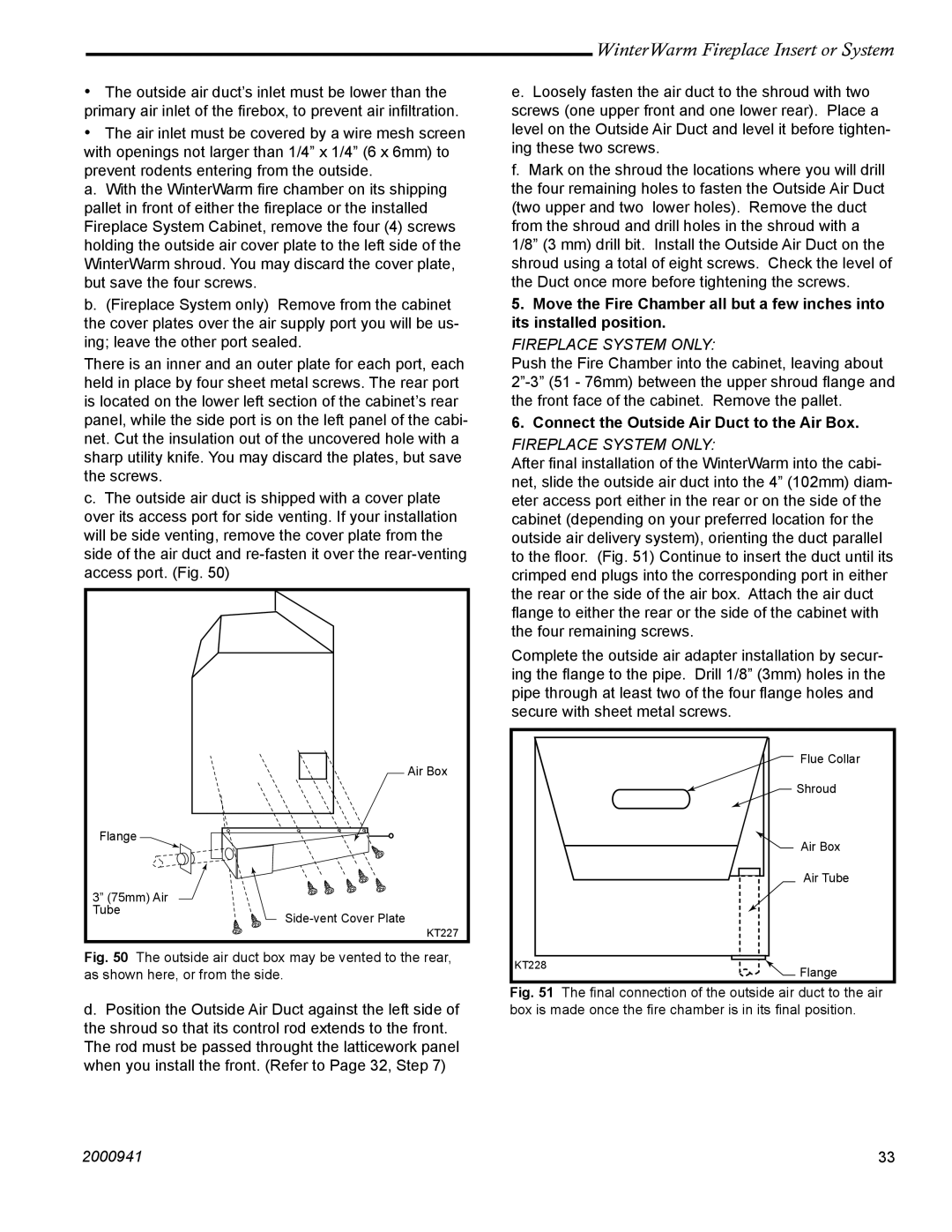
a. With the WinterWarm fire chamber on its shipping pallet in front of either the fireplace or the installed Fireplace System Cabinet, remove the four (4) screws holding the outside air cover plate to the left side of the WinterWarm shroud. You may discard the cover plate, but save the four screws.
b.(Fireplace System only) Remove from the cabinet the cover plates over the air supply port you will be us- ing; leave the other port sealed.
There is an inner and an outer plate for each port, each held in place by four sheet metal screws. The rear port is located on the lower left section of the cabinet’s rear panel, while the side port is on the left panel of the cabi- net. Cut the insulation out of the uncovered hole with a sharp utility knife. You may discard the plates, but save the screws.
c.The outside air duct is shipped with a cover plate over its access port for side venting. If your installation will be side venting, remove the cover plate from the side of the air duct and
Air Box
Flange |
|
3” (75mm) Air |
|
Tube | |
|
KT227
Fig. 50 The outside air duct box may be vented to the rear, as shown here, or from the side.
d.Position the Outside Air Duct against the left side of the shroud so that its control rod extends to the front. The rod must be passed throught the latticework panel when you install the front. (Refer to Page 32, Step 7)
WinterWarm Fireplace Insert or System
e.Loosely fasten the air duct to the shroud with two screws (one upper front and one lower rear). Place a level on the Outside Air Duct and level it before tighten- ing these two screws.
f.Mark on the shroud the locations where you will drill the four remaining holes to fasten the Outside Air Duct (two upper and two lower holes). Remove the duct from the shroud and drill holes in the shroud with a 1/8” (3 mm) drill bit. Install the Outside Air Duct on the shroud using a total of eight screws. Check the level of the Duct once more before tightening the screws.
5.Move the Fire Chamber all but a few inches into its installed position.
FIREPLACE SYSTEM ONLY:
Push the Fire Chamber into the cabinet, leaving about
6. Connect the Outside Air Duct to the Air Box.
FIREPLACE SYSTEM ONLY:
After final installation of the WinterWarm into the cabi- net, slide the outside air duct into the 4” (102mm) diam- eter access port either in the rear or on the side of the cabinet (depending on your preferred location for the outside air delivery system), orienting the duct parallel to the floor. (Fig. 51) Continue to insert the duct until its crimped end plugs into the corresponding port in either the rear or the side of the air box. Attach the air duct flange to either the rear or the side of the cabinet with the four remaining screws.
Complete the outside air adapter installation by secur- ing the flange to the pipe. Drill 1/8” (3mm) holes in the pipe through at least two of the four flange holes and secure with sheet metal screws.
| Flue Collar |
| Shroud |
| Air Box |
| Air Tube |
KT228 | Flange |
|
Fig. 51 The final connection of the outside air duct to the air box is made once the fire chamber is in its final position.
2000941 | 33 |