If you have installed the optional outside air kit, pass the control rod through the latticework at this time. (Fig. 53)
Seat the front against the Fire Chamber assembly, and attach with the six
Make sure the front seats properly before tightening the cap screws; the edge of the front should be almost even with the side and top plates, protruding no more than 1/16” (2mm).
Tighten the left and right sides before tightening the top screws. Tighten the cap screws that attach the upper grille. NOTE: If the front has been installed too far for- ward, the door gasket may not make the required seal and the fire may be difficult to control.
Step 8. Attach the Rheostat Rod Linkages
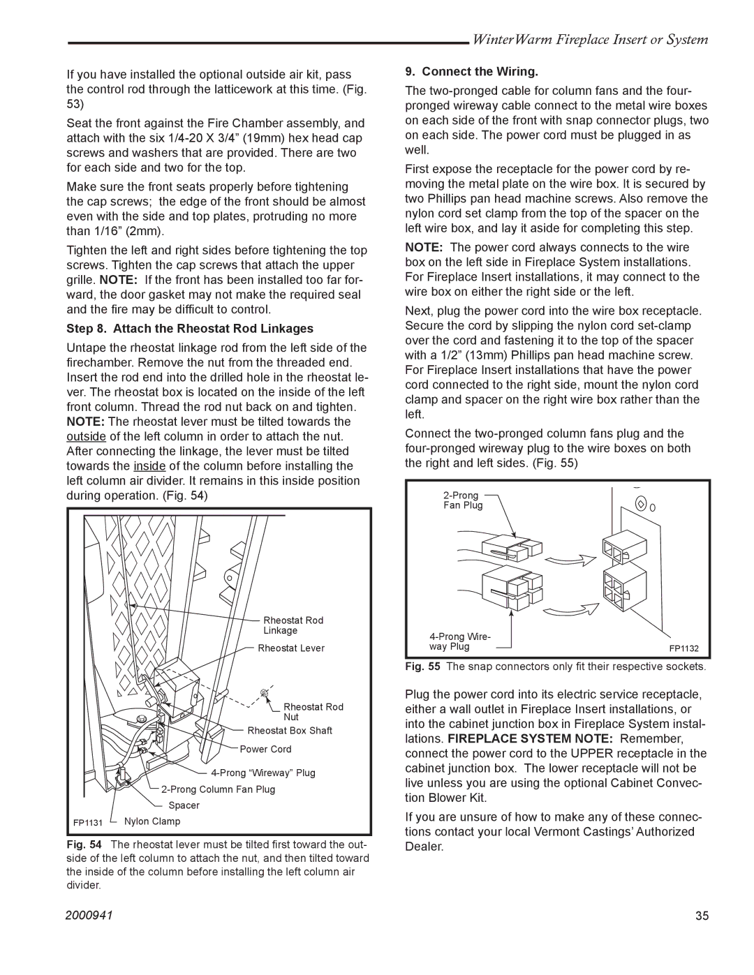
Untape the rheostat linkage rod from the left side of the firechamber. Remove the nut from the threaded end. Insert the rod end into the drilled hole in the rheostat le- ver. The rheostat box is located on the inside of the left front column. Thread the rod nut back on and tighten. NOTE: The rheostat lever must be tilted towards the outside of the left column in order to attach the nut. After connecting the linkage, the lever must be tilted towards the inside of the column before installing the left column air divider. It remains in this inside position during operation. (Fig. 54)
| Rheostat Rod |
| Linkage |
| Rheostat Lever |
| Rheostat Rod |
| Nut |
| Rheostat Box Shaft |
| Power Cord |
| |
| |
| Spacer |
FP1131 | Nylon Clamp |
Fig. 54 The rheostat lever must be tilted first toward the out- side of the left column to attach the nut, and then tilted toward the inside of the column before installing the left column air divider.
WinterWarm Fireplace Insert or System
9. Connect the Wiring.
The
First expose the receptacle for the power cord by re- moving the metal plate on the wire box. It is secured by two Phillips pan head machine screws. Also remove the nylon cord set clamp from the top of the spacer on the left wire box, and lay it aside for completing this step.
NOTE: The power cord always connects to the wire box on the left side in Fireplace System installations. For Fireplace Insert installations, it may connect to the wire box on either the right side or the left.
Next, plug the power cord into the wire box receptacle. Secure the cord by slipping the nylon cord
Connect the
| |
way Plug | FP1132 |
Fig. 55 The snap connectors only fit their respective sockets.
Plug the power cord into its electric service receptacle, either a wall outlet in Fireplace Insert installations, or into the cabinet junction box in Fireplace System instal- lations. FIREPLACE SYSTEM NOTE: Remember, connect the power cord to the UPPER receptacle in the cabinet junction box. The lower receptacle will not be live unless you are using the optional Cabinet Convec- tion Blower Kit.
If you are unsure of how to make any of these connec- tions contact your local Vermont Castings’ Authorized Dealer.
2000941 | 35 |