Assembly Step 3
Locate these parts:
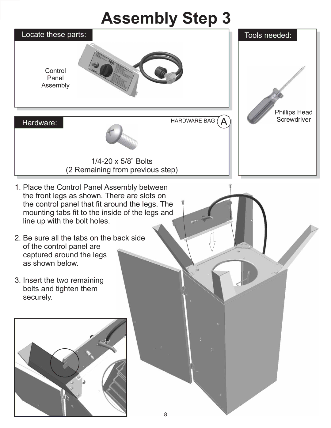
Control
Panel
Assembly
Hardware: | HARDWARE BAG A |
(2 Remaining from previous step)
1.Place the Control Panel Assembly between the front legs as shown. There are slots on the control panel that fit around the legs. The mounting tabs fit to the inside of the legs and line up with the bolt holes.
2.Be sure all the tabs on the back side of the control panel are
captured around the legs as shown below.
3.Insert the two remaining bolts and tighten them securely.
Tools needed:
Phillips Head
Screwdriver
8