3-Wire Power Cord Installation
(See Figures 3.1, 3.2 and 3.3)
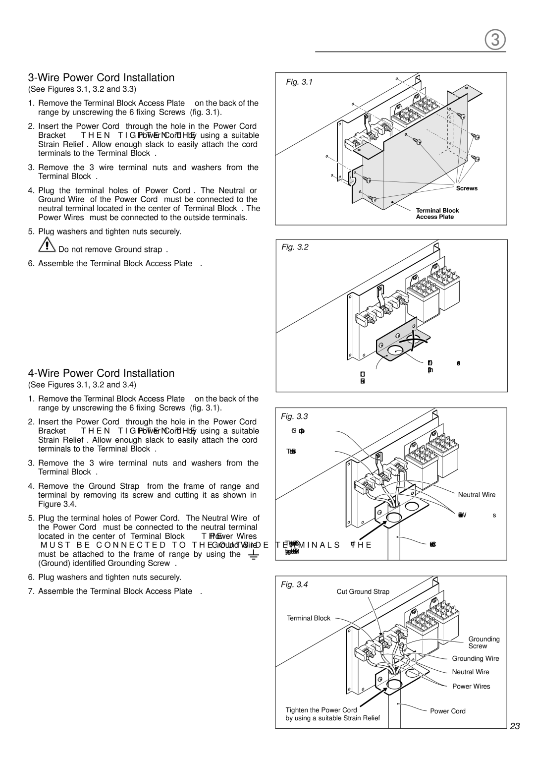
1. | Remove the Terminal Block Access Plate on the back of the |
| range by unscrewing the 6 fixing Screws (fig. 3.1). |
2. | Insert the Power Cord through the hole in the Power Cord |
| Bracket; then tighten the Power Cord by using a suitable |
| Strain Relief. Allow enough slack to easily attach the cord |
| terminals to the Terminal Block. |
3. | Remove the 3 wire terminal nuts and washers from the |
| Terminal Block. |
4. | Plug the terminal holes of Power Cord. The Neutral or |
| Ground Wire of the Power Cord must be connected to the |
| neutral terminal located in the center of Terminal Block. The |
| Power Wires must be connected to the outside terminals. |
5. | Plug washers and tighten nuts securely. |
Fig. 3.1
![]() Screws
Screws
Terminal Block
Access Plate
Do not remove Ground strap. |
6. Assemble the Terminal Block Access Plate. |
(See Figures 3.1, 3.2 and 3.4)
Fig. 3.2
Power Cord
Bracket
Hole D 1" 9/64 (29 mm)
1. | Remove the Terminal Block Access Plate on the back of the | |||||||
| range by unscrewing the 6 fixing Screws (fig. 3.1). | |||||||
2. | Insert the Power Cord through the hole in the Power Cord | |||||||
| Bracket; then tighten the Power Cord by using a suitable | |||||||
| Strain Relief. Allow enough slack to easily attach the cord | |||||||
| terminals to the Terminal Block. | |||||||
3. | Remove the 3 wire terminal nuts and washers from the | |||||||
| Terminal Block. | |||||||
4. | Remove the Ground Strap from the frame of range and | |||||||
| terminal by removing its screw and cutting it as shown in | |||||||
| Figure 3.4. | |||||||
5. | Plug the terminal holes of Power Cord. The Neutral Wire of | |||||||
| the Power Cord must be connected to the neutral terminal | |||||||
| located in the center of Terminal Block; the Power Wires | |||||||
| must be connected to the outside terminals; the Ground Wire | |||||||
| must be attached to the frame of range by using the |
|
|
|
|
|
|
|
|
|
|
|
|
|
|
| |
| (Ground) identified Grounding Screw. |
|
|
|
| |||
|
|
| ||||||
6. | Plug washers and tighten nuts securely. | |||||||
Fig. 3.3
Ground strap
Terminal Block
Tighten the Power Cord
by using a suitable Strain Relief
Neutral Wire
Power Wires
![]() Power Cord
Power Cord
7. Assemble the Terminal Block Access Plate. |
Fig. 3.4
Cut Ground Strap
Terminal Block
Grounding
Screw
Grounding Wire
Neutral Wire
Power Wires
Tighten the Power Cord | Power Cord |
by using a suitable Strain Relief |
|
23