PROGRAM SECTION
3 | 2 | 1 | 4 | 5 | 6 | 7 |
8 |
|
|
|
|
|
|
12 |
|
|
|
|
|
|
| 9 | 10 |
| 14 13 11 | ||
iISOLATOR ON/OFF SWITCH
When set to "OFF", a full range signal is transmitted regardless of the position of any isolator controls.
oHI PASS FILTER SWITCH
On each PGM is a Hi Pass Filter Switch. Pressing this switch activates the high pass filter and when on the indicator LED will illuminate. The cut off frequencies for this filter can be adjusted by the SWEEP volume rotary dial !1. If this switch is pressed simultaneously with the Low Pass Filter switch the resulting effect is a Notch Pass Filter.
!0LOW PASS FILTER SWITCH
On each PGM is a LOW pass filter switch. Pressing this switch activates the low pass filter for that PGM. When on the indicator LED will be illuminated and this filter will remove sound frequencies below the cut off point. The cut off point can be adjusted by using the SWEEP volume rotary dial !1. If this switch is pressed simultaneously with the High Pass Filter switch the resulting effect is a Notch Pass Filter.
!1SWEEP VOLUME
This rotary dial is used to adjust the filter cut off points on each PGM. A rotation to the left will result in a movement away from the High frequencies towards the Low frequencies. Vice versa a movement to the right will result in a movement away from the Low frequencies towards the High frequencies.
CROSS FADER
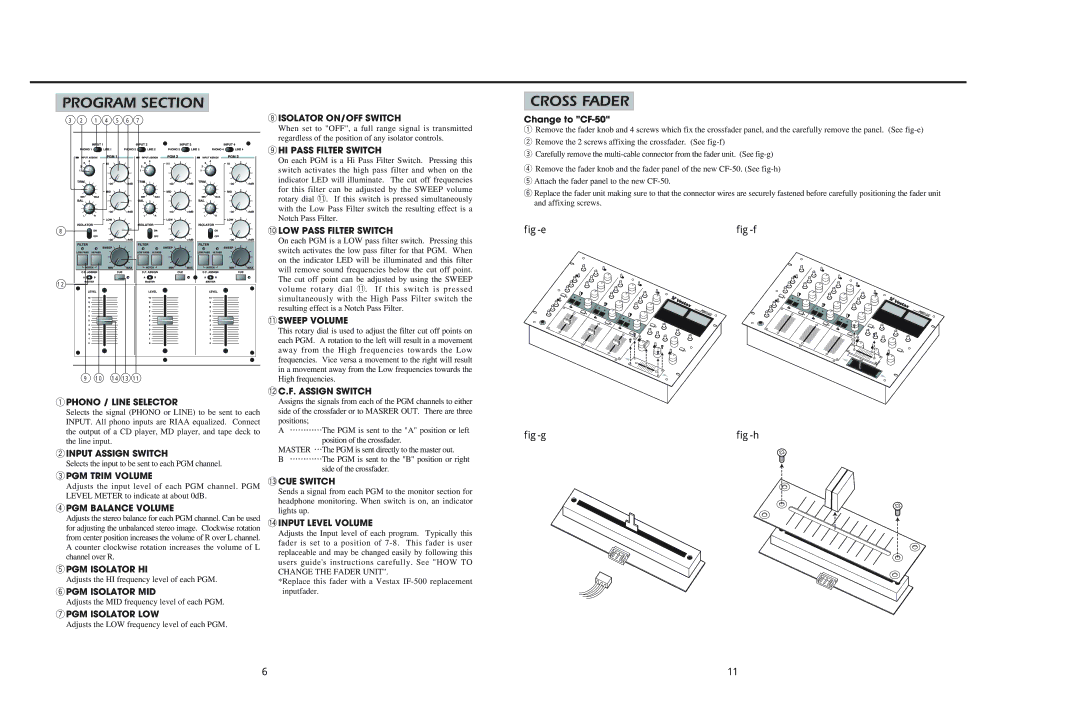
Change to "CF-50"
qRemove the fader knob and 4 screws which fix the crossfader panel, and the carefully remove the panel. (See
wRemove the 2 screws affixing the crossfader. (See
eCarefully remove the
rRemove the fader knob and the fader panel of the new
tAttach the fader panel to the new
yReplace the fader unit making sure to that the connector wires are securely fastened before carefully positioning the fader unit and affixing screws.
|
|
qPHONO / LINE SELECTOR
Selects the signal (PHONO or LINE) to be sent to each INPUT. All phono inputs are RIAA equalized. Connect the output of a CD player, MD player, and tape deck to the line input.
wINPUT ASSIGN SWITCH
Selects the input to be sent to each PGM channel.
ePGM TRIM VOLUME
Adjusts the input level of each PGM channel. PGM LEVEL METER to indicate at about 0dB.
rPGM BALANCE VOLUME
Adjusts the stereo balance for each PGM channel. Can be used for adjusting the unbalanced stereo image. Clockwise rotation from center position increases the volume of R over L channel. A counter clockwise rotation increases the volume of L channel over R.
tPGM ISOLATOR HI
Adjusts the HI frequency level of each PGM.
yPGM ISOLATOR MID
Adjusts the MID frequency level of each PGM.
uPGM ISOLATOR LOW
Adjusts the LOW frequency level of each PGM.
!2C.F. ASSIGN SWITCH
Assigns the signals from each of the PGM channels to either side of the crossfader or to MASRER OUT. There are three positions;
A⋯⋯⋯⋯The PGM is sent to the "A" position or left position of the crossfader.
MASTER ⋯The PGM is sent directly to the master out.
B⋯⋯⋯⋯The PGM is sent to the "B" position or right side of the crossfader.
!3CUE SWITCH
Sends a signal from each PGM to the monitor section for headphone monitoring. When switch is on, an indicator lights up.
!4INPUT LEVEL VOLUME
Adjusts the Input level of each program. Typically this fader is set to a position of
*Replace this fader with a Vestax
|
|
6 | 11 |