HOW TO CHANGE THE FADER UNIT
INPUT FADER
Change to "IF-500"
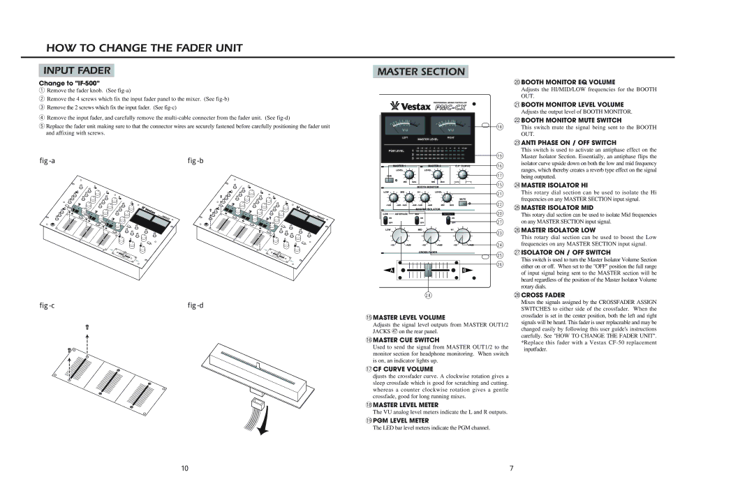
qRemove the fader knob. (See
wRemove the 4 screws which fix the input fader panel to the mixer. (See
eRemove the 2 screws which fix the input fader. (See
rRemove the input fader, and carefully remove the
tReplace the fader unit making sure to that the connector wires are securely fastened before carefully positioning the fader unit and affixing with screws.
|
|
MASTER SECTION
@0BOOTH MONITOR EQ VOLUME
Adjusts the HI/MID/LOW frequencies for the BOOTH
OUT.
| @1BOOTH MONITOR LEVEL VOLUME |
| Adjusts the output level of BOOTH MONITOR. |
| @2BOOTH MONITOR MUTE SWITCH |
18 | This switch mute the signal being sent to the BOOTH |
| OUT. |
@3ANTI PHASE ON / OFF SWITCH
| This switch is used to activate an antiphase effect on the | |
19 | Master Isolator Section. Essentially, an antiphase flips the | |
16 | isolator curve upside down on both the low and mid frequency | |
ranges, which thereby creates a reverb type effect on the signal | ||
17 | ||
being outputted. | ||
15 | @4MASTER ISOLATOR HI | |
21 | This rotary dial section can be used to isolate the Hi | |
| frequencies on any MASTER SECTION input signal. |
22 | @5MASTER ISOLATOR MID | |
20 | ||
This rotary dial section can be used to isolate Mid frequencies | ||
27 | on any MASTER SECTION input signal. |
23 |
24 |
25 |
26 |
@6MASTER ISOLATOR LOW
This rotary dial section can be used to boost the Low frequencies on any MASTER SECTION input signal.
@7ISOLATOR ON / OFF SWITCH
This switch is used to turn the Master Isolator Volume Section either on or off. When set to the "OFF" position the full range of input signal being sent to the MASTER section will be heard regardless of the position of the Master Isolator Volume rotary dials.
|
|
28
!5MASTER LEVEL VOLUME
Adjusts the signal level outputs from MASTER OUT1/2 JACKS $7on the rear panel.
!6MASTER CUE SWITCH
Used to send the signal from MASTER OUT1/2 to the monitor section for headphone monitoring. When switch is on, an indicator lights up.
@8CROSS FADER
Mixes the signals assigned by the CROSSFADER ASSIGN SWITCHES to either side of the crossfader. When the crossfader is set in the center position, both the left and right signals will be heard. This fader is user replaceable and may be changed easily by following this user guide's instructions carefully. See "HOW TO CHANGE THE FADER UNIT". *Replace this fader with a Vestax
!7CF CURVE VOLUME
djusts the crossfader curve. A clockwise rotation gives a sleep crossfade which is good for scratching and cutting. whereas a counter clockwise rotation gives a gentle crossfade, good for long running mixes.
!8MASTER LEVEL METER
The VU analog level meters indicate the L and R outputs.
!9PGM LEVEL METER
The LED bar level meters indicate the PGM channel.
10 | 7 |
