3.Assemble the plastic handle as shown in Figure 1.
4.Tools required: Allen Wrench.
![]() Be sure that the welder’s electri- cal power supply cord is not connected while performing this procedure.
Be sure that the welder’s electri- cal power supply cord is not connected while performing this procedure.
5.Install MIG gun per instructions.
6.Install welding wire per instructions.
7.Place the power source in a well ventilated area. DO NOT obstruct the air intake and output vents. A reduced air flow can cause a reduced duty cycle and damage internal com- ponents.
8.Insure at least 6 feet of open space on the side of the welder.
Figure 1: Feet and Handle Installation
![]() Avoid contacts with wires or parts. DO NOT work with the side panels partially opened or removed completely from the power source.
Avoid contacts with wires or parts. DO NOT work with the side panels partially opened or removed completely from the power source.
MIG GUN INSTALLATION
This unit uses a Firepower MIG Gun furnished with rear connections that fit directly into the wire drive assem- bly. These guns are referred to as “Direct Connect” MIG Guns and are easy to install. Firepower “Direct Connect” MIG Guns are designed specifically for use with the Firepower Welding Systems.
1. Remove the gun liner cover from the wire feeder by removing the two
 DO NOT remove the screws at the front of the wire feeder.
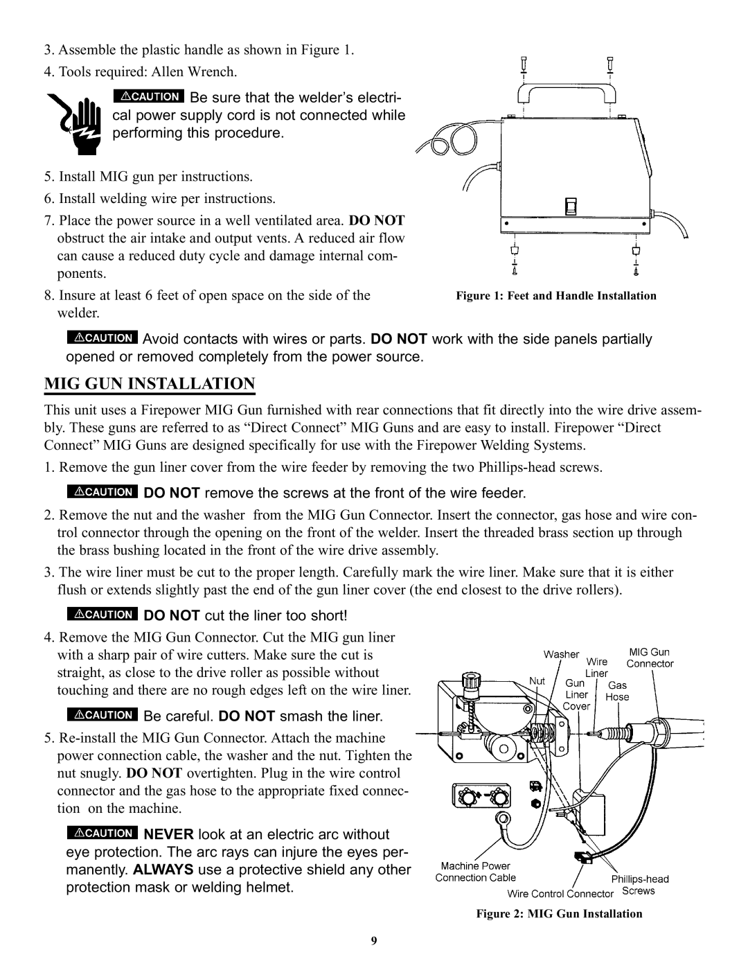
2.Remove the nut and the washer from the MIG Gun Connector. Insert the connector, gas hose and wire con- trol connector through the opening on the front of the welder. Insert the threaded brass section up through the brass bushing located in the front of the wire drive assembly.
3.The wire liner must be cut to the proper length. Carefully mark the wire liner. Make sure that it is either flush or extends slightly past the end of the gun liner cover (the end closest to the drive rollers).
 DO NOT cut the liner too short!
4.Remove the MIG Gun Connector. Cut the MIG gun liner with a sharp pair of wire cutters. Make sure the cut is straight, as close to the drive roller as possible without touching and there are no rough edges left on the wire liner.
 Be careful. DO NOT smash the liner.
5.
![]() NEVER look at an electric arc without eye protection. The arc rays can injure the eyes per- manently. ALWAYS use a protective shield any other protection mask or welding helmet.
NEVER look at an electric arc without eye protection. The arc rays can injure the eyes per- manently. ALWAYS use a protective shield any other protection mask or welding helmet.
Figure 2: MIG Gun Installation
9