![]() When changing the wire diameter being used, or replacing the wire feed roll, be sure that the correct groove for the wire diameter selected is inside, closest to the machine. The wire is driven by the inside groove. Feed rolls are marked on the side identifying the nearest groove. Feed rolls installed on the FP 120, FP 130, FP 160 are marked "0.6" on one side. When this side is inside, closest to the machine, the groove is suitable for use with 0.023" (0.6mm) hard wire. The other side is marked "0.8". When this side is inside, closest to the machine, the groove is suitable for use with 0.030" (0.8mm) hard wire and 0.035" (0.9mm) flux core wire.
When changing the wire diameter being used, or replacing the wire feed roll, be sure that the correct groove for the wire diameter selected is inside, closest to the machine. The wire is driven by the inside groove. Feed rolls are marked on the side identifying the nearest groove. Feed rolls installed on the FP 120, FP 130, FP 160 are marked "0.6" on one side. When this side is inside, closest to the machine, the groove is suitable for use with 0.023" (0.6mm) hard wire. The other side is marked "0.8". When this side is inside, closest to the machine, the groove is suitable for use with 0.030" (0.8mm) hard wire and 0.035" (0.9mm) flux core wire.
6.Connect the power supply cable to the power output line. Turn on the switch. Press the torch switch. The wire fed by the wire feeding motor at variable speed must slide through the liner. When it exits from the torch neck, release the torch switch. Turn off the machine. Mount the contact tip and the nozzle.
![]() The rolls, when moving, may crush the fingers. Periodically, check the rolls. Replace them when they are worn and compromise the regular feeding of the wire.
The rolls, when moving, may crush the fingers. Periodically, check the rolls. Replace them when they are worn and compromise the regular feeding of the wire.
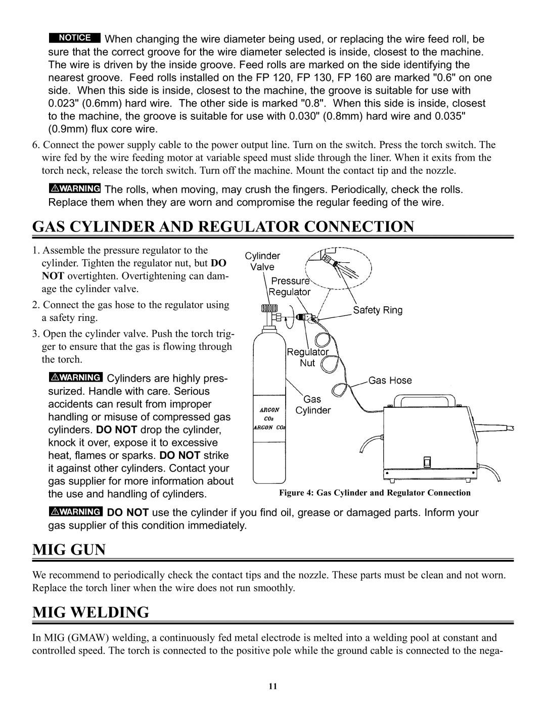
GAS CYLINDER AND REGULATOR CONNECTION
1.Assemble the pressure regulator to the cylinder. Tighten the regulator nut, but DO NOT overtighten. Overtightening can dam- age the cylinder valve.
2.Connect the gas hose to the regulator using a safety ring.
3.Open the cylinder valve. Push the torch trig- ger to ensure that the gas is flowing through the torch.
![]() Cylinders are highly pres- surized. Handle with care. Serious accidents can result from improper handling or misuse of compressed gas cylinders. DO NOT drop the cylinder, knock it over, expose it to excessive heat, flames or sparks. DO NOT strike it against other cylinders. Contact your gas supplier for more information about
Cylinders are highly pres- surized. Handle with care. Serious accidents can result from improper handling or misuse of compressed gas cylinders. DO NOT drop the cylinder, knock it over, expose it to excessive heat, flames or sparks. DO NOT strike it against other cylinders. Contact your gas supplier for more information about
the use and handling of cylinders. | Figure 4: Gas Cylinder and Regulator Connection |
![]() DO NOT use the cylinder if you find oil, grease or damaged parts. Inform your gas supplier of this condition immediately.
DO NOT use the cylinder if you find oil, grease or damaged parts. Inform your gas supplier of this condition immediately.
MIG GUN
We recommend to periodically check the contact tips and the nozzle. These parts must be clean and not worn. Replace the torch liner when the wire does not run smoothly.
MIG WELDING
In MIG (GMAW) welding, a continuously fed metal electrode is melted into a welding pool at constant and controlled speed. The torch is connected to the positive pole while the ground cable is connected to the nega-
11